P.8
P.9
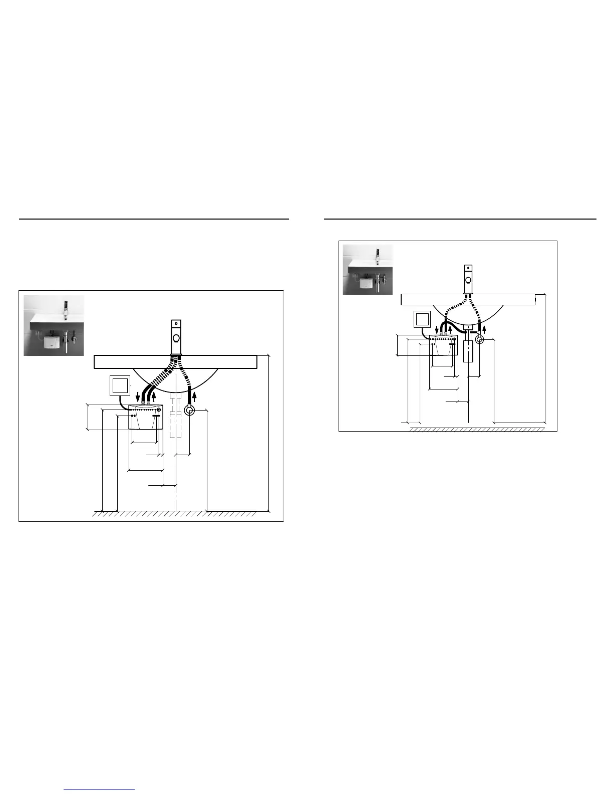
“Pressure-resistant (closed) installation with standard tap” (dimensions in mm)
3.2 Installation instructions
The heater is installed as shown in the immediate vicinity of the outlet in a frost-free room. We guarantee
trouble-free operation only if CLAGE ttings and accessories are used.
Note the following during installation:
• Installation must comply with DIN VDE 0100 and EN 806 and with the statutory regulations of the country
and the provisions of the local electricity and water supply company.
• Check technical data and the information on the rating plate under the cover.
• Ensure that all accessories are removed from the packing materials.
• Easy access to the appliance shall be guaranteed at all times. An external shut-off valve has to be installed.
• Thoroughly rinse the water pipes before connection.
• Optimum operation is ensured at a water ow pressure of 0.2 to 0.4 MPa (2–4 bar). The appliance must
not be subjected to pressure exceeding 1 MPa (10 bar).
• For safe operation of this instantaneous water heater, a non return valve is not required. If, nevertheless,
a non return valve has to be installed, it may only be placed in the hot water outlet line behind the instan-
taneous water heater.
• The minimum requirements for the required water resistance must be complied with. The required water
resistance of the can be obtained from your water supply company.
3.Installation
3.1.2 Pressure-resistant (closed) outlet installations
Angle valve outlet G ½”
Angle valve approx. 550
Top edge of basin approx. 850
133
22 75
186
≧70
Electrical connection with
mains power cable
(shorten if necessary)
Cable inlet approx. 553
135
Fastening approx. 520
“Vented (open) installation with a special open-outlet tap” (dimensions in mm)
Angle valve outlet G ½”
Angle valve approx. 550
Top edge of basin approx. 850
133
22 75
186
≧70
Electrical connection with
mains power cable
(shorten if necessary)
Cable inlet approx. 553
135
Fastening approx. 520
3.Installation
Installation, initial operation and maintenance of this appliance must only be conducted by an authorised
professional, who will then be responsible for adherence to applicable standards and installation regulations.
We assume no liability for any damages caused by failure to observe these instructions!
3.1 Typical installations
3.1.1 Vented (open) installation