Installation examples
LRGT 16-1, LRGT 16-2, LRGT 17-1
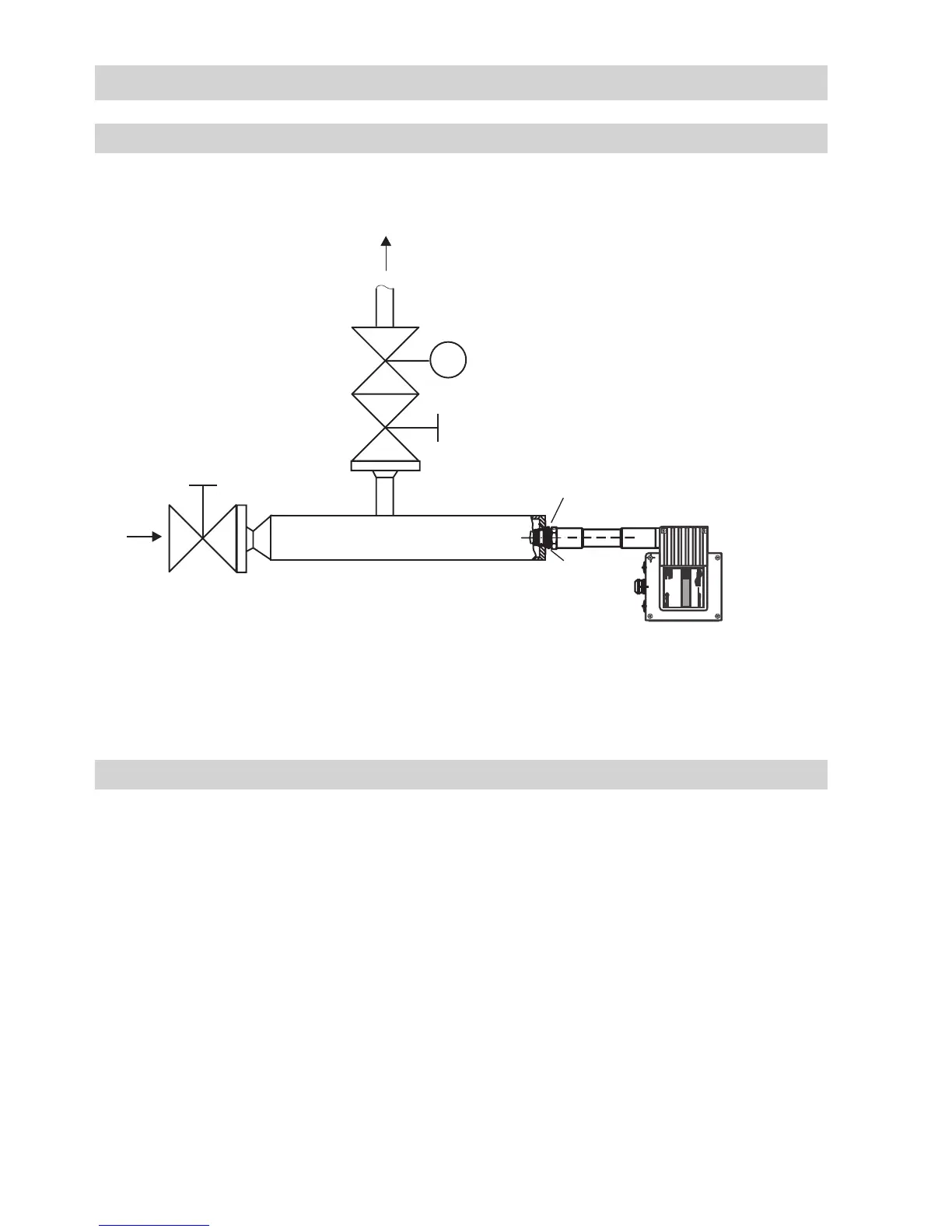
Fig. 8
Conductivity monitoring and continuous boiler blowdown, installation of conductivity transmitter in the
blowdown line via a separate level pot
d
c
DN 15-40
Outlet
Inlet
DN 15-40
e
a
LRGT 16-1
LRGT 16-2
LRGT 17-1
G 1 A, ISO 228
Key
0 Boiler drum
a Sealing ring 33 x 39, form D, DIN 7603,
1.4301, bright annealed
b T-type connector,
provided on boiler, DN 50
c Shut-off valve GAV
d Continuous blowdown valve BAE
e Level pot
f Cover screws (cross recess head screws M4)
g Housing cover
h EMC cable gland M 20 x 1.5
i Fixing nut for terminal box
j Code switch
k LED 1 green
l LED 2 red
m Terminal lugs for electrode wires,
functional earth
n Terminal strip
o Fixing screw for electronic circuit board
p Connection for functional earth
continued
continued
 Loading...


