1
2
2
3
1
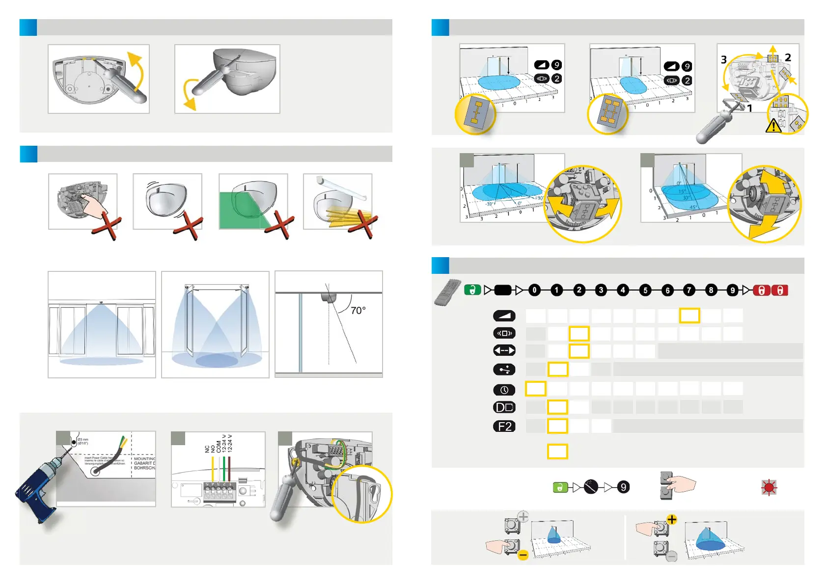
OPENING THE SENSOR
MOUNTING & WIRING
Before fi xing After fi xing
TIPS
Apply the mounting template.
Drill 1 hole for the cable and
pull it through.
Drill 2 holes for the screws.
Position the
cable as indicated.
Fix the sensor fi rmly.
Avoid proximity to neon
lamps or moving objects.
Do not cover the sensor.Avoid vibrations.Do not touch electronical
parts.
APPLICATIONS
Connect the wires accordingly:
1 - BROWN - POWER SUPPLY
2 - GREEN - POWER SUPPLY
3 - WHITE - COM
4 - YELLOW - NO
5 - YELLOW - NC
Wall mounting above sliding or
revolving door
Ceiling mounting in front of door
(sliding, revolving or swing doors)
Mounting on door axis (swing doors)
or
3
4
P
A
XXS XS S > > > > L XL XXL
1 2
>>>>>
... S,
XS, XXS
... L, XL, XXL
< 3 m > 3 m
+
MECHANICAL ADJUSTMENTS
SETTINGS
(by remote control or push buttons)
FIELD SIZE
FIELD SIZE
IMMUNITY FILTER
DETECTION MODE
OUTPUT
CONFIGURATION
bi = two-way detection; uni = one-way detection towards sensor
A = active output (NO-contact)
P = passive output (NC-contact)
bi uni
uni
PRM
FACTORY VALUES
low
normal
Adjust the lateral antenna
angle.
Adjust the vertical antenna
angle.
OR
RESETTING TO FACTORY VALUES:
4 m x 2 m (wide)
2 m x 2.5 m (narrow)
WIDTHANGLE
uni
AWAY
PRM &
AWAY
uni PRM = one-way detection also of people with reduced mobility
uni AWAY = one-way detection away from sensor
HOLD-OPEN TIME
MOUNTING
HEIGHT
DOOR CONTROL
0.5 s 1 s 2 s 3 s 4 s 5 s 6 s 7 s 8 s 9 s
< 3 m > 3 m
auto
open closed
open = the sensor detects constantly. The LED is ON.
closed = the sensor is in standby and does not detect. The LED is OFF.
2.2 m
2.2 m
high
> 2 seconds
2.2 m
2.2 m
highest
 Loading...