Do you have a question about the GEZE TS 5000 L-E-ISM VPK and is the answer not in the manual?
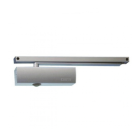
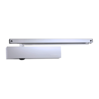
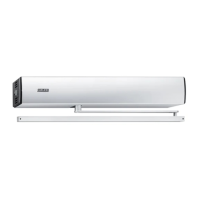
Describes the system's function, including electrical hold-open devices and closing sequence control.
Refers to additional documents for installation and connection, which are supplied with the system.
Explains warning symbols like DANGER (danger for people) and CAUTION (information for workflow).
Explains symbols for important notes, additional information, and user actions.
Provides drilling templates for direct fixing or using a mounting plate, with dimensions for band spacing.
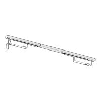
Detailed steps for mounting guide rails and covers, including alignment, adjustment pieces, and fixing.
Instructions for preparing the electrical connection, including mounting spacers and boards.
Steps for connecting the 24V fixed-leaf cable of the electrical hold-open device to the supply terminal.
Instructions for connecting the 24V mains cable to the terminal and securing it with a cable tie.
Detailed steps for mounting the wire rope, including threading, tensioning, and shortening.
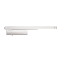
Instructions for mounting the sliding lever to the fixed leaf and connecting it to the sliding block.
Details mounting the sliding lever to the moving leaf, similar to the fixed leaf procedure.
Guides the adjustment of the trigger unit, including regulating screws and checking congruence with markers.
Steps for adjusting the electrical hold-open device, including positioning, securing, and checking movement.
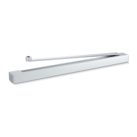
Instructions for mounting cover panels, ensuring cables are not pinched and inserting inspection caps.
Describes the procedure for the first operation and a function test, including switching on power and checking hold-open engagement.
Outlines the acceptance test procedure for systems used with a hold-open device, requiring authorized personnel.
| Brand | GEZE |
|---|---|
| Model | TS 5000 L-E-ISM VPK |
| Category | Door Opening System |
| Language | English |