EasyManua.ls Logo

GF Signet 9900 User Manual

GF Signet 9900
12 pages
To Next Page IconTo Next Page
Page #1 background imageLoading...
Page #1 background image
Signet 9900 Conductivity Transmitter
English
The Signet 9900 Conductivity System provides a single-channel interface for
Conductivity/Resistivity and Salinity measurement.
The 9900 is available in either Panel or Field Mount. Both versions require
10.8 to 35.2 VDC power (24 VDC nominal).
Operating Instructions
System is compatible with any of the sensors shown below:
3-2819-1 (198 844 010)
0.01 cell constant, 316 SS electrode, ¾ in. threads for in-line installations only
3-2819-S1 (159 000 085)
0.01 cm-1 316 SS electrode, Sanitary Tri-clamp ange 1 to 1½ in.
3-2820-1 (198 844 000)
0.1 cm-1 316 SS electrode, ¾ in. threads in-line only
3-2821-1 (198 844 001)
1.0 cm-1 316 SS electrode, ¾ in. threads in-line only
3-2822-1 (198 844 002)
10 cm-1 316 SS electrode with xed ¾ in. threads in-line or submersible
mounting only
Your system may also be wired to a special order sensor with any of the following features.
High Temperature and Pressure options.
Wetted materials (Hastelloy-C, Monel and Titanium) and sensor lengths.
Wet-Tap, ball valve retractable sensor for long insertion length.
Description
Compatibility
Panel Mount
Field Mount
English
中文
*Need manual part #.090*
3-9900-1P-1.090 Rev. 0 08/18

Other manuals for GF Signet 9900

Question and Answer IconNeed help?

Do you have a question about the GF Signet 9900 and is the answer not in the manual?

GF Signet 9900 Specifications

General IconGeneral
ModelGF Signet 9900
CategoryTransmitter
Enclosure RatingNEMA 4X/IP65
Output4 to 20 mA
MaterialPBT
ApprovalsCE
LanguagesEnglish, French, German, Spanish, Italian

Summary

Operating Instructions

Product Description

Summarizes the Signet 9900 Conductivity Transmitter's function and application.

System Compatibility

Lists compatible sensors, features, and options for the 9900 system.

Safety, Warranty, and Registration

Safety Information and Warnings

Details hazard indicators, safety precautions, and PPE recommendations.

Warranty and Product Registration

Information on product warranty terms, return procedures, and online registration.

Module and Standards Information

Module Installation Procedures

Instructions and precautions for installing plug-in modules into the base unit.

Standards and Approvals

Lists product certifications, compliance standards, and regulatory information.

Installation Procedures

Panel Mount Installation Guide

Step-by-step instructions for preparing and mounting the transmitter in a panel.

Field Mount Installation Options

Guidance on using mounting kits for installing the transmitter in field applications.

Wiring and Connections

Wiring Tips and Best Practices

Essential guidelines and precautions for correctly wiring the transmitter.

Terminal Identification and Usage

Detailed explanation of each terminal's function for power, signals, and outputs.

Sensor and Output Wiring

Sensor Wiring Diagram

Illustrates how to connect the conductivity sensor module to the transmitter.

Relay and Open Collector Wiring

Instructions for wiring relay modules and open collector outputs for alarms or control.

Operation and System Setup

Front Panel Operation and Display

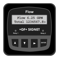
Explanation of display segments, indicator LEDs, and menu navigation keys.

System Setup and Configuration

Procedures for entering edit mode, navigating menus, and configuring system settings.

Ordering Information

Product Part Numbers and Options

Lists part numbers for the base unit and optional modules for ordering.

Related product manuals