12
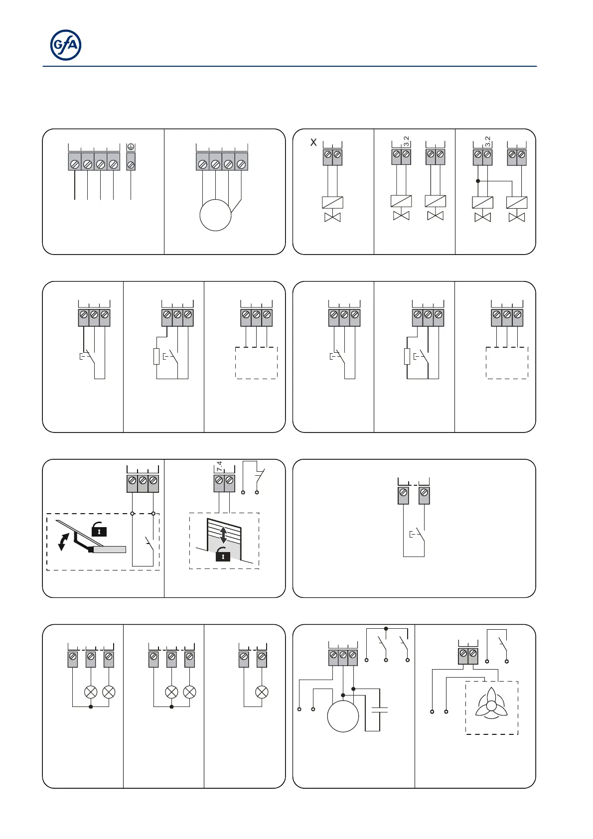
1 Terminal diagram
X1 Supply X2 Hydraulic motor X3 Dock leveller valves
1.1
1.2
1.3
1.4
L
2
L
1
L
3
NPE
X
①
2.1
2.2
2.3
2.4
VUWPE
X
M
3~
1
②
3.2
3.1
+-
Y
1
ⓐ
3.1
+-
Y
1
3.4
3.3
+
-
Y
2
X
ⓑ
3.1
+-
Y
1
3.4
3.3
+
-
Y
2
X
ⓒ
3~ 400V, N, PE M
1
: Motor Hinged lip Extendible lip Extendible lip
X5 Wheel chock sensor X6 Vehicle detector
5.1
5.2
5.3
S
1
ⓐ
X
S
1
R
1
5.1
5.2
5.3
ⓑ
X
A
1
5.1
5.2
5.3
+
-
S
ⓒ
X
6.1
6.2
6.3
S
2
ⓐ
X
S
2
R
2
6.1
6.2
6.3
ⓑ
X
A
2
6.1
6.2
6.3
+
-
S
ⓒ
X
S
1
: Changeover R
1
: 8k2 A
1
: Sensor S
2
: Changeover R
2
: 8k2 A
2
: Sensor
Resistance Sensor unit Resistance Sensor unit
S
1
: NO contact 24V DC S
2
: NO contact 24V DC
X7 Ramp/door unlock X8 Dock leveller position sensor
7.1
7.2
7.3
X
K
R
A
4
7.5
A
4
X
K
T
8.1
8.2
X
S
3
A
4
: Door controller A
4
: Door controller S
3
: NO
K
R
: NO (floating) K
T
: NO (floating)
X9 Traffic light indicators / lighting X10 Vehicle shelter
9.1
9.2
9.3
H
1
H
2
①
X
9.4
9.5
9.6
H
4
H
3
②
X
9.7
9.8
H
5
③
X
10.1
10.2
10.3
M
1~
2
UZ
NL
U1 Z1
C
B
K
Z1
K
U1
X
X
10.4
10.5
A
3
K
L
NL
ext traffic light int traffic light lighting C
B
: Operating capacitor A
3
: Fan controller
H
1
: Red H
3
: Red H
5
: Headlamp M
2
: Tubular motor 1~ 230V, K
L
: NO contact (floating)
H
2
: Green H
4
: Green K
U1
: NO (floating)
K
Z1
: NO (floating))