Appendix B Accessories
VFD-E Series
Revision August 2006, 01EE, SW--PW V1.03/CTL V2.03 B-19
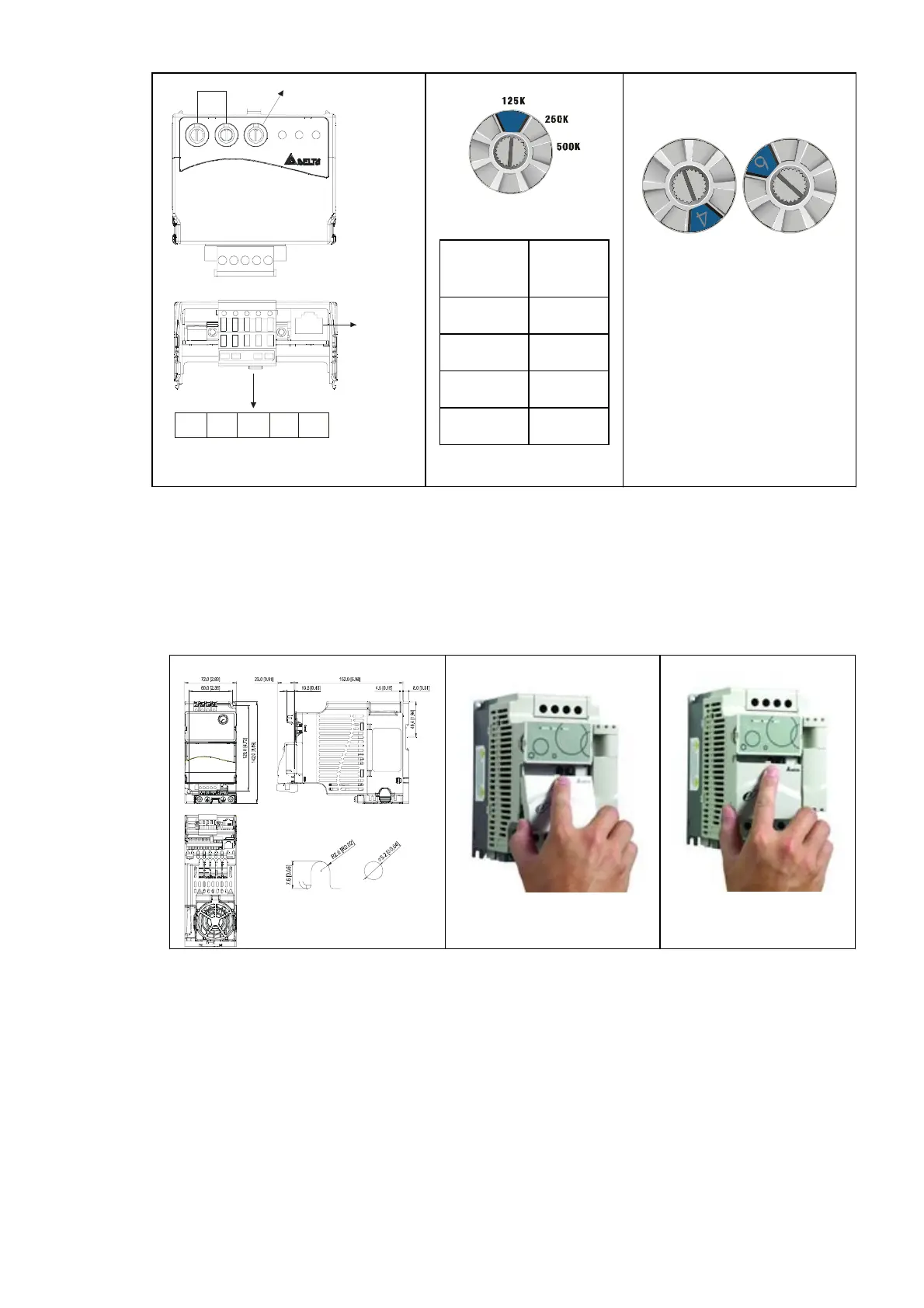
CME-DN01
ADD1 ADD2
SP
500K
250K
125K
BAUD
MODNET
MAC address Date Rate
CAN-L
V+
Empty
Pin
CAN-H
V-
1: Reserved
2: EV
5: SG+
6: Reserved
7: Reserved
8: Reserved
3: GND
4: SG-
Setting baud rate
BAUD
0
Switch
Value
Baud
Rate
0 125K
1 250K
2 500K
Other AUTO
Setting MAC addresses:
use decimal system.
ADD1
ADD2
B.10.1.3 Mounting Method
Step1 and step2 show how to mount this communication module onto VFD-E. The
dimension on the left hand side is for your reference.
Dimensions
UNIT: mm(inch)
STEP 1
STEP 2
B.10.1.4 Power Supply
No external power is needed. Power is supplied via RS-485 port that is connected to
VFD-E. An 8 pins RJ-45 cable, which is packed together with this communication
module, is used to connect the RS-485 port between VFD-E and this communication
module for power. This communication module will perform the function once it is
connected. Refer to the following paragraph for LED indications.
B.10.1.5 LEDs Display


 To Next Page
 Loading...