3
0798ML Dicembre 2015 - December 2015
Termoregolazione wireless
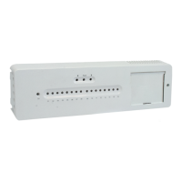
Modulo di controllo wireless PM100w
Wireless control unit PM100W
ISO
14001
0032A/3
OHSAS
18001
0064L/1
ISO
9001
0006/7
047U54518
Sensore temperatura acqua calda sanitaria. La funzione è
disponibile unicamente quando il touch-screen KD400Y002 e la
sonda K563PY002 sono collegati al modulo PM100W.
Se questa funzione è attivata, il canale di uscita 16 viene gestito secondo
i seguenti parametri: temperatura preimpostata del bollitore, orario e
temperatura rilevata dalla sonda collegata al modulo PM100W.
Detector of the sanitary hot water temperature. The function is just available
when the KD400Y002 LCD touchscreen and this detector are connected.
If this function is active, the output channel 16 is managed by the following
parameters: pre-set temperature of the boiler, time and temperature detected by
the sensor connected to the PM100W unit.
Contatto allarme. (Non disponibile).
Alarm contact. (not available).
Connettori per interfaccia di comunicazione (8). Serve per il
collegamento di un solo touch-screen KD400Y002 e di un massimo di
3 moduli PM100WY002. Questa combinazione permette quindi di controllare
48 uscite indipendenti.
Connectors for communication interface (8). It serves for the connection
of no more than one KD400Y002 LCD touchscreen and the linking of up to 3
PM100WY002 units to each other. This combination creates a kit which has up to
48 independent outputs.
Nota. Note.
• La distanza minima tra i ricevitori / trasmettitori è di 2 m.
• Quando più moduli sono collegati tra loro, è necessario l’utilizzo del
KD400Y002.
• È possibile collegare un solo KD400Y002.
• Usare un cavo UTP diritto normale per eettuare il collegamento.
Lunghezza massima 200 m.
• The minimum distance between receivers / transmitters is 2 m.
• When the units are connected to each other, then using the KD400Y002
is always necessary.
• Just one KD400Y002 can be connected to the PM100WY002 main unit or
to a group of these units.
• Use a common straight UTP cable for connection. Maximum length 200 m.
Connettore per antenna esterna. (Non disponibile) Per ottenere una
migliore portata RF per i componenti wireless, è possibile collegare
un’antenna esterna al modulo di controllo. Questa operazione può essere
eseguita solo mediante il display KD400Y002. Far passare il cavo per l’antenna
attraverso il pressacavo (3).
Connector for an external antenna. (Not available) For getting a better RF
range for wireless components an external antenna (5) can be plugged into the
main unit. Enabling this option can only be done by the KD400Y002. Put the cable
for the antenna through the gland (3).
maximum is reached then the unit activates output pulse switching mode. This
allows the distribution of the maximum current to every single thermo-electric
valve. Thanks to the valves inertia this switching has no negative inuence (the
only eect which it has is a little bit slower opening of the valves). In combination
with electric relays it could have a negative inuence because of permanent
switching on/o.
Nota. Note.
I canali di uscita non sono progettati per commutare i dispositivi che
possono controllare parti semiconduttrici.
The output channels are not designed to switch devices which can control
semiconductor parts.
Terminali di uscita Bus. Servono per i collegamenti Bus (sensore
magnetico Bus non disponibile). I dispositivi Bus possono essere
collegati solo quando il modulo di controllo è completamente
disconnessa dalla rete elettrica.
Bus output terminals serves for Bus device connection (Bus magnetic
detector, not available). The Bus devices can only be connected when the
main unit is completely disconnected from the mains power.
Modalità emergenza. I terminali di entrata servono per bloccare
l’attivazione di tutte le uscite (6) contemporaneamente.
NO (normalmente aperto di default): i canali di uscita 1-16 vengono
accesi/spenti secondo i segnali dei termostati. NC (normalmente
chiuso): tutti i canali sono spenti. Un canale viene attivato solo se il termostato
registra un calo di temperatura inferiore alla temperatura di emergenza
(Stby). Uno stato di emergenza viene indicato dal LED ON (4). La modalità
di emergenza può essere attivata anche via wireless. Quando il termostato
programmabile è sul canale “ON”, può bloccare il riscaldamento secondo il
calendario settimanale predenito. Le opzioni e i principi di associazione sono
descritti nel capitolo “Associazione dei dispositivi”.
Emergency mode. Input terminals serve for blocking the activation of all
outputs (6) at the same time. NO (normally open from default): output channels
1-16 are turned on/o according to the signals from thermostats. NC (normally
closed): All channels are turned o. A channel is activated only if the thermostat
measures a temperature drop under the Emergency (Stby) temperature. An
emergency status is indicated by the “ON” LED (4). An emergency mode can
also by activated wirelessly. When the programmable thermostat is assigned
to the “ON” channel then it can block the heating according to the pre-dened
weekly calendar. Options and enrolling principles can be found in the chapter:
“Enrolling devices”.
Termostato di sicurezza. Terminali per la sonda K563PY002, che
riesce a rilevare quando si verica un superamento della
temperatura del uido di riscaldamento di 65 °C, disattivando
contestualmente tutti i 16 canali di uscita. Può essere usato in
modo pratico per proteggere il sistema radiante e i circuiti quando la
temperatura del uido è troppo elevata, evitando così di danneggiare
l’impianto. Se questo sensore non è collegato, l’unità non ore questa
funzione.
Safety thermostat. Terminals for the K563PY002 detector which can detect
exceeding a heating medium temperature of 65°C and at this moment turn
o all 16 output channels. A practical use is for protecting the under-oor
heating system and circuits when the heating medium is superheated to avoid
damaging the system. If this detector is not connected, the unit doesn´t oer
this function.
 Loading...