• Be sure to connect fan cables to the fan headers to prevent your CPU and system from overheat-
ing. Overheating may result in damage to the CPU or the system may hang.
• Thesefanheadersarenotcongurationjumperblocks.Donotplaceajumpercapontheheaders.
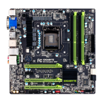
3/4)CPU_FAN/SYS_FAN1/SYS_FAN2/SYS_FAN3(FanHeaders)
All fan headers on this motherboard are 4-pin. Most fan headers possess a foolproof insertion design.
Whenconnectingafancable,besuretoconnectitinthecorrectorientation(theblackconnectorwireis
thegroundwire).Thespeedcontrolfunctionrequirestheuseofafanwithfanspeedcontroldesign.For
optimum heat dissipation, it is recommended that a system fan be installed inside the chassis.
CPU_FAN:
PinNo. Denition
1 GND
2 +12V
3 Sense
4 Speed Control
SYS_FAN1/SYS_FAN2/SYS_FAN3:
PinNo. Denition
1 GND
2 Speed Control
3 Sense
4 VCC
SYS_FAN1/SYS_FAN2
SYS_FAN3
CPU_FAN
1
5) SATA30/1/2/3/4/5(SATA6Gb/sConnectors)
The SATA connectors conform to SATA 6Gb/s standard and are compatible with SATA 3Gb/s and SATA 1.5Gb/s
standard. Each SATA connector supports a single SATA device. The Intel
®
Chipset supports RAID 0, RAID 1,
RAID5,andRAID10.RefertoChapter3,"ConguringSATAHardDrive(s),"forinstructionsonconguring
a RAID array.
• ARAID0orRAID1congurationrequiresatleasttwoharddrives.Ifmorethantwoharddrives
are to be used, the total number of hard drives must be an even number.
• ARAID5congurationrequiresatleastthreeharddrives.(Thetotalnumberofharddrivesdoes
nothavetobeanevennumber.)
• ARAID10congurationrequiresfourharddrives.
• To enable hot-plugging for the SATA ports, refer to Chapter 2, "BIOS Setup," "Peripherals\SATA
Conguration,"formoreinformation.
PinNo. Denition
1 GND
2 TXP
3 TXN
4 GND
5 RXN
6 RXP
7 GND
SATA3
1 0
3 2
5 4
7
 Loading...