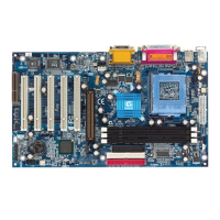
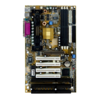
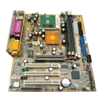
6WMM7 Series Motherboard
3-10
The CPU speed must match with the frequency RATIO. It will cause
system hanging up if the frequency RATIO is higher than that of CPU.
Note: Please set the CPU host frequency in accordance with your
processor’s specifications. We don’t recommend you to set the
system bus frequency over the CPU’s specification because these
specific bus frequencies are not the standard specifications for
CPU, chipset and most of the peripherals. Whether your system
can run under these specific bus frequencies properly will depend
on your hardware configurations, including CPU, Chipsets,
SDRAM, Cards ….etc.
Note: JP33 is only available when the motherboard use 82810E
chipset.
3.6. CMOS RTC & ISA CFG CMOS RAM
There're RTC & CMOS RAM on board; they have a power supply from external
battery to keep the DATA inviolate & effective. The RTC is a REAL-TIME
CLOCK device, which provides the DATE & TIME to system. The CMOS RAM
is used for keeping the information of system configuration, so the system can
automatically boot OS every time. Since the lifetime of internal battery is 5 years,
the user can change a new Battery to replace old one after it cannot work.
Danger of explosion if battery is incorrectly replaced.
Replace only with the same or equivalent type recommended by the
manufacturer.
Dispose of used batteries according to the manufacturer’s instructions.
3.7. SPEAKER CONNECTOR INSTALLATION
There is a speaker in AT system for sound purpose. The 4 - Pins connector
SPK is used to connect speaker.
3.8. HARDWARE RESET SWITCH CONNECTOR INSTALLATION
The RESET switch on panel provides users with HARDWARE RESET function.
The system will do a cold start after the RESET switch is pushed and released
by user. The RESET switch is a 2 PIN connector and should be installed to RES
on main board.

 Loading...


