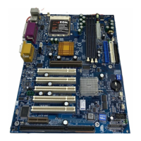
7ZMM Series Motherboard Layout
6
Page Index for CPU Speed Setup/Connectors/Panel and Jumper Definition
Page
CPU Speed Setup P. 7
SW1 P. 7
Connectors P. 8
ATX Power P.8
COM A / VGA / LPT Port P.8
Floppy Connector P.9
Game & Audio Port P.9
IDE 1(Primary) / IDE 2(Secondary) Connector P.10
J2 (System Fan) P.10
J3 (CPU Fan) P.11
J7 (AUX_IN) P.11
J8 (TEL) P.12
J9 (CD Audio Line In) P.12
J12 (Wake On LAN) P.13
J13 (Ring Power On) P.13
JP2 (Front Audio) P.14
JP6 (Power Fan) P.14
JP8 / LED1 (DIMM LED Connector & DIMM LED) P.15
PS/2 Keyboard & PS/2 Mouse Port P.15
USB1 (Rear USB Port) P.16
USB2 (Front USB Connector) P.16
Panel and Jumper Definition P.17
BAT1 (Battery) P.17
J11 (2x11 Pins Front Panel) P.17
J16/J17/J18 (AMR Select) [Optional] P.18
JP1 (Front MIC Function) P.19
JP3 (Clear CMOS Function) [Optional] P.19
JP4 (USB Device Wake up Selection) P.20
JP7 (STR Function Enable) P.20
JP9 (BIOS Write Protect Function) P.21
JP10 (CPU Clock Frequency) [Optional] P.21
JP11 (Onboard Sound Function Selection) P.22
 Loading...