GA-8S661GXMP(-C) Motherboard - 18 -
English
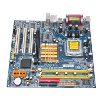
SYS_FAN
1
Pin No. Definition
1 GND
2 +12V
3 Sense
1
CPU_FAN
3/4) CPU_FAN / SYS_FAN (Cooler Fan Power Connector)
The cooler fan power connector supplies a +12V power voltage via a 3-pin power connector and
possesses a foolproof connection design.
Most coolers are designed with color-coded power connector wires. A red power connector wire
indicates a positive connection and requires a +12V power voltage. The black connector wire is
the ground wire (GND).
Please remember to connect the power to the cooler to prevent system overheating and failure.
Caution!
Please remember to connect the power to the CPU fan to prevent CPU overheating and failure.
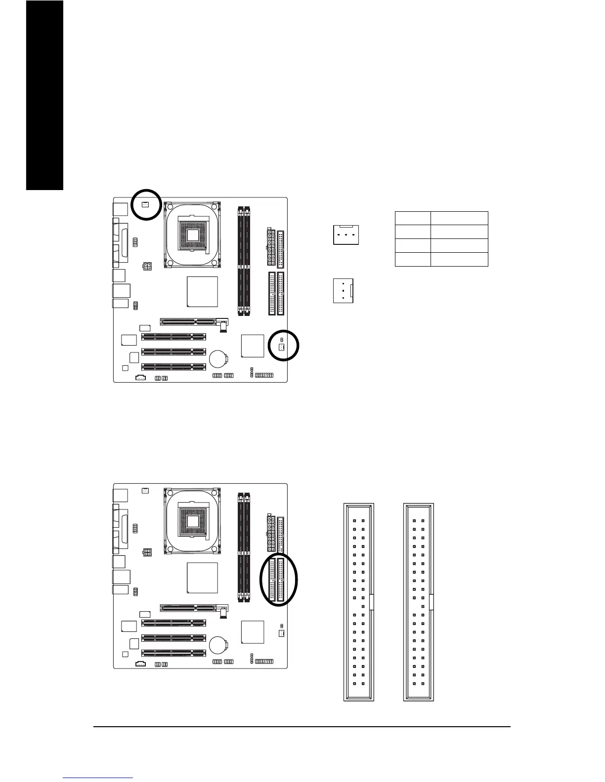
5) IDE1/IDE2 (IDE Connector)
An IDE device connects to the computer via an IDE connector. One IDE connector can connect to one
IDE cable, and the single IDE cable can then connect to two IDE devices (hard drive or optical drive). If
you wish to connect two IDE devices, please set the jumper on one IDE device as Master and the other
as Slave (for information on settings, please refer to the instructions located on the IDE device).
40
21
40 39
21
39
IDE2 Connector IDE1 Connector
 Loading...