Do you have a question about the Gigabyte GA-H61TN and is the answer not in the manual?
Information about GIGABYTE's documentation types, including the User's Manual.
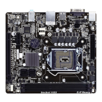
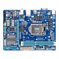
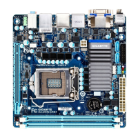
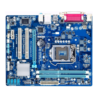
Details on supported CPUs, LGA1155 package, and Intel H77/B75/H61 chipsets.
Information on DDR3 memory support, HDMI, DisplayPort, and LVDS connectors.
Specifications for Realtek ALC887 audio, GbE LAN, PCI Express, and Mini PCI Express slots.
Details on SATA 6Gb/s, SATA 3Gb/s, and mSATA connectors for different models.
Details on USB 3.0/2.0 ports available on the back panel and internal headers.
Listing and description of internal connectors like CPU fan, SATA, USB, and front panel headers.
Details on back panel connectors including HDMI, DisplayPort, USB, and audio jacks.
Information on system voltage, temperature, fan speed monitoring, and BIOS flash/features.
Details on OS support and the Thin Mini-ITX form factor dimensions.
Guidelines for safely installing the CPU and CPU cooler, including thermal paste application.
Instructions for installing RAM modules and expansion cards, emphasizing safety precautions.
Connection instructions for DC power and details on RJ-45 LAN port LED states.
Information on DisplayPort and HDMI interfaces, including resolution and audio support.
Guidelines for using USB 3.0 and USB 2.0 ports with various devices.
Description of Line Out (Green) and MIC In (Pink) jacks for audio connectivity.
Pin assignments for connecting chassis front panel components like power, reset, and LEDs.
Pin definitions for SATA0 (6Gb/s and 3Gb/s) connectors.
Pin definitions for SATA1 (6Gb/s and 3Gb/s) connectors.
Pin definitions for SATA2 (3Gb/s) connectors.
Pin definitions for SATA3 (3Gb/s) connectors.
Pin definitions for the FUSB2_1 USB 2.0/1.1 header.
Pin definitions for FUSB2_2, FUSB2_3, FUSB2_5 USB 2.0/1.1 headers.
Pin assignments for the front panel audio header supporting HD and AC'97 audio.
Pin definitions for Flat Panel Display Headers used for backlight control.
Pin definitions for LVDS headers used for low-voltage differential signaling.
Information on 4-pin fan headers for CPU and system fans, including speed control.
Pin definitions for the digital microphone header.
Details of the 2-pin power connector for integrated 19V chassis power supply.
Pin definitions for the flat panel display switch header.
Pin definitions for the back light switch header used for screen adjustment.
Pin assignments for the speaker header for system startup beep codes.
Information on the battery connector and precautions for battery replacement.
Instructions for using the CLR_CMOS jumper to reset BIOS values to factory defaults.
Configuration of jumpers for different screen voltage settings for LVDS.
Jumper settings for selecting operating voltage for the backlight panel.
Pin definitions for connecting a WiFi operation indicator LED.
Instructions for connecting the SATA power connector to SATA devices.
How to enter the BIOS Setup program by pressing the F2 key during POST.
Explanation of function keys used for navigation and control within the BIOS Setup utility.
Overview of the Main menu items and Advanced menu for enhanced features.
Details on Chipset configuration, boot sequence, and system security settings.
Explanation of options to save changes, discard changes, and exit the BIOS Setup.
Instructions on using arrow keys and Enter to navigate and select items in the Main Menu.
On-screen descriptions and how to access advanced options via Ctrl+F1.
Information shown in the Main Menu: BIOS Vendor, version, date, memory, etc.
Explanation of BIOS Vendor, Core Version, Compliancy, and Project Version fields.
Details on BIOS Build Date/Time, MAC Address, Total Memory, and Memory Frequency.
How to select and enter submenus within the Advanced menu for hardware configuration.
Option to enable or disable DDR over voltage for memory configuration.
Setting the highest ACPI sleep state (S1, S3) for system standby.
Display of CPU type, signature, speed, cores, and cache information.
Information on Intel Hyper-Threading, VT-x, and SMX technologies support.
Explanation of the Execute Disable Bit for protection against buffer overflow attacks.
Configuration of Intel Virtualization Technology for running multiple OS or for Directed I/O.
Options to configure SATA controllers as IDE, RAID, or AHCI mode.
Identifying Serial ATA and mSATA types of hard disks installed in the computer.
Enabling/disabling Intel Rapid Start Technology for faster system resume.
Configuring S3 RTC Wake entry and entry timer for Rapid Start Technology.
Enabling or disabling warnings for CPU/System fan failures.
Enabling or disabling the smart fan control function for CPU and system fans.
Displaying real-time system/CPU temperature and fan speeds (RPM).
Enabling or disabling the Intel Smart Connect Technology.
Enabling or disabling network booting for OS installation.
Enabling or disabling IPv4 and IPv6 PXE support for network booting.
Configuration of Intel SpeedStep Technology (EIST) and Turbo Mode for CPU performance.
Enabling CPU C3/C6 states for enhanced power saving during system halt.
Displaying driver information and configuring Realtek ethernet controller parameters.
Configuring onboard audio (Azalia), Verb Table, and onboard LAN controller.
Enabling ERP support and configuring system behavior after AC power loss.
Enabling or disabling the LVDS control function for display connectivity.
Setting Bootup NumLock State, Fast Boot, and boot drive priorities.
Configuring boot order for hard drives, optical drives, and other bootable devices.
Enabling/disabling CSM and selecting boot OS types (UEFI/Legacy).
Configuring UEFI or legacy option ROM for LAN and storage controllers.
Selecting UEFI or legacy option ROM for the video controller.
Setting UEFI or legacy option ROM priority for other PCI devices.
Setting Administrator and User passwords to protect BIOS access and system boot.
Displaying system mode and configuring Secure Boot for enhanced system integrity.
Defining the Secure Boot Mode as Standard or Custom.
Options to save changes and exit, or discard changes and exit the BIOS setup.
Options to save or discard changes and reset the system.
Loading default BIOS settings by selecting the Restore Defaults option.
Saving current settings as user defaults or restoring previously saved user defaults.
Configuring the boot device or launching EFI Shell from a filesystem device.
| Memory voltage | 1.5 V |
|---|---|
| Memory channels | Dual-channel |
| Memory slots type | SO-DIMM |
| Number of memory slots | 2 |
| Supported memory types | DDR3-SDRAM |
| Maximum internal memory | 8 GB |
| Supported memory clock speeds | 800, 1066, 1333, 1600 MHz |
| Processor socket | LGA 1155 (Socket H2) |
| Processor manufacturer | Intel |
| Compatible processor series | Intel Celeron, Intel Pentium |
| Processor thermal power (max) | 65 W |
| Intel® Core i3/i5/i7/i9 series | i3-3xxx, i5-3xxx, i7-3xxx |
| CPU fan connector | Yes |
| USB 2.0 connectors | 4 |
| Number of SATA connectors | - |
| Number of SATA II connectors | 3 |
| USB 3.2 Gen 1 (3.1 Gen 1) connectors | 0 |
| HDMI version | 1.3a |
| USB 2.0 ports quantity | USB 2.0 ports have a data transmission speed of 480 Mbps, and are backwards compatible with USB 1.1 ports. You can connect all kinds of peripheral devices to them. |
| Audio chip | Realtek ALC887 |
| Cooling type | Passive |
| Component for | Nettop |
| Power source type | ATX |
| Motherboard chipset | Intel® H61 |
| PC health monitoring | CPU, FAN, Power supply, Temperature |
| Audio output channels | 7.1 channels |
| Motherboard form factor | mini ITX |
| Windows operating systems supported | Windows 7 Home Basic, Windows 7 Home Basic x64, Windows 7 Home Premium, Windows 7 Home Premium x64, Windows 7 Professional, Windows 7 Professional x64, Windows 7 Starter, Windows 7 Starter x64, Windows 7 Ultimate, Windows 7 Ultimate x64, Windows 8, Windows 8 Enterprise, Windows 8 Enterprise x64, Windows 8 Pro, Windows 8 Pro x64, Windows 8 x64 |
| Supported storage drive interfaces | SATA II |
| DirectX version | 11 |
| Parallel processing technology support | Not supported |
| Ethernet interface type | Gigabit Ethernet |
| BIOS type | EFI AMI |
| ACPI version | 2.0a |
| BIOS memory size | 64 Mbit |
| Width | 170 mm |
|---|