Hardware Installation- 33 -
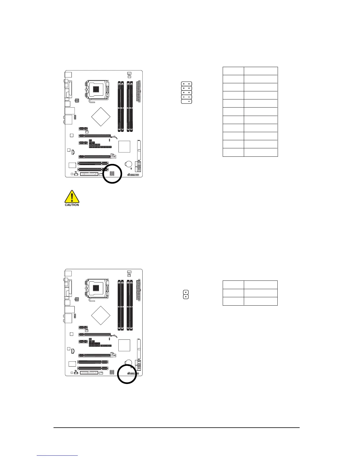
17) F_USB1/F_USB2 (USB Headers, Yellow)
The headers conform to USB 2.0/1.1 specification. Each USB header can provide two USB ports
via an optional USB bracket. For purchasing the optional USB bracket, please contact the local
dealer.
Pin No. Definition
1 Power (5V)
2 Power (5V)
3 USB DX-
4 USB DY-
5 USB DX+
6 USB DY+
7 GND
8 GND
9 No Pin
10 NC
• Do not plug the IEEE 1394 bracket (2x5-pin) cable into the USB header.
• Prior to installing the USB bracket, be sure to turn off your computer and unplug the
power cord from the power outlet to prevent damage to the USB bracket.
12
910
18) CI1 (Chassis Intrusion Header)
This motherboard provides a chassis detection feature that detects if the chassis cover has been
removed. This function requires a chassis with chassis intrusion detection design.
Pin No. Definition
1 Signal
2 GND
1
 Loading...