No. Code Descripon
6 USB3_MLAN Server Management LAN Port (top)
USB 3.0 Ports (Boom)
7 SYS_FAN1 System Fan Connector #1
8 LAN1_2 GbE LAN Port #1 (top)/Port #2 (boom)
9 SW_PWR Power Buon(top)/ID Buon (Boom)
10 P12V_AUX1 2 x 4 Pin Power Connector (for CPU)
11 CPU0_FAN CPU Fan Connector
12 P12V_AUX2 2 x 4 Pin Power Connector (for Memory)
13 PMBUS PMBus Connector
14 BAT1 System Baery
15 SL_CN1 SlimLine 4i Connector #1 (SATA Signal)
16 SL_CN2 SlimLine 4i Connector #2 (SATA Signal)
17 SL_CN3 SlimLine 4i Connector #3 (SATA Signal)
18 SL_CN4 SlimLine 4i Connector #4 (SATA Signal)
19 ATX1 2 x 13 Pin System Power Connector
20 CASE_OPEN Case Open Intrusion Header
21 FP_1 Front Panel Header
22 BP_1 HDD Back Plane Board Connector
23 F_USB3 Front Panel USB 3.0 Connector
24 IPMB IPMB Connector
25 SYS_FAN5 System Fan Connector #5
26 SYS_FAN4 System Fan Connector #4
27 SYS_FAN3 System Fan Connector #3
28 SYS_FAN6 System Fan Connector #6
29 COM2 Serial Port Cable Connector #2
30 PCIE_1 PCIe x 16 Slot #1
31 M2_0 M.2 Connector
(PCIe Gen3 x4, NGFF-2280, M-Key)
32 PCIE_3 PCIe x 16 Slot #3
33 PCIE_4 PCIe x 8 Slot #4
34 PCIE_5 PCIe x 16 Slot #5
35 PCIE_7 PCIe x 16 Slot #7
36 LED_BMC BMC Firmware Readiness LED
37 COM1 Serial Port Cable Connector #1
No. Code Descripon
1 VGA VGA Port
2 10GLAN1 10G LAN Port #1 (MZ01-CE0 Only)
3 LPC_TPM TPM Module Connector
4 10GLAN2 10G LAN Port #2 (MZ01-CE0 Only)
5 SYS_FAN2 System Fan Connector #2
Front Panel Header / 前面板
HDD Back Plane Board Header/ 硬盤背板排針
No. Pin Define
1 Power LED+
3 No Pin
5 Power LED-
7 HDD LED+
(Reserved for Gigabyte System)
9 HDD LED-
(Reserved for Gigabyte System)
11 Power Buon
13 GND
15 Reset Buon
17 GND
19 No Connect
21 GND
23 NMI Switch
No. Pin Define
2 5V Standby
4 ID LED+
6 ID LED-
8 System Status LED+
10 System Status LED-
12 LAN1 Acve LED+
14 LAN1 Link LED-
16 SMBus Data
18 SMBus Clock
20 Case Open
22 LAN2 Acve LED+
24 LAN2 Link LED-
2
23
24
1
No. Pin Define
1 Reserved
2 BP_SGDIN
3 GND
4 BP_SGDOUT
5 BP_SGLD
6 GND
7 BP_SGCLK
8 PLD_Program_EN
9 GLED_AMB_N
10 GLED_GRN_N
11 FAN_IRQ_N
12 Reserved
13 BP_SCL
14 GND
15 BP_SDA
1 2
29 30
No. Pin Define
16 BP_RST_N
17 SMB_U2_TMP_SCL
18 GND
19 SMB_U2_TMP_SDA
20 I2C_DEV_RST
21 RSVD
22 GND
23 Reserved
24 GND
25 Reserved
26 GND
27 Reserved
28 GND
29 P_3V3_AUX
30 P_3V3_AUX
ATX Power/ 电源
No. Pin Define
1 GND
2 GND
3 GND
4 GND
5 +12V
6 +12V
7 +12V
8 +12V
24
12
13
1
No. Pin Define
1 3.3V
2 3.3V
3 GND
4 +5V
5 GND
6 +5V
7 GND
8 Power Good
9 5VSB
10 +12V
11 +12V
12 3.3V
8 4
5 1
1 5
4
8
No. Pin Define
13 3.3V
14 -12V
15 GND
16 PS_ON
17 GND
18 GND
19 GND
20 -5V
21 +5V
22 +5V
23 +5V
24 GND
P12V_AUX1 P12V_AUX2
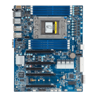
Installing CPU/ 安装 CPU
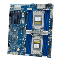
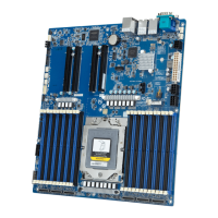
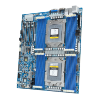
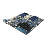
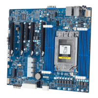
Motherboard Components
3
1
2
1
External cap
2
3
CPU
4
5
6
7
1
3
2
8
9
3
1
2
4
NOTE!
When installing the heatsink to CPU,
use T20-Lobe driver to ghten 4 capve nuts
in sequence as 1-4.
The screw ghtening torque:
16.1 ± 1.2 kgf-cm (14.0± 1.0 lbf-in)
Memory Populaon Configuraon/ 安装内存
RDIMM Maximum Frequency Supported Table
Slots
DIMMs
Populated
DIMM
1R
2
2
1
--
--
--
--
--
--
2667
2400
Not Supported
Not Supported
Not Supported
Not Supported
2133
2133
2133
1
1 1
1
1
1
1
--
--
-- --
2667
2667
Not Supported
1
1
1
2
2
--
----
--
1
1
1 1
2
4DR 1.2V
2R
2DR
Frequency (MT/s)
LRDIMM Maximum Frequency Supported Table
Slots
DIMMs
Populated
DIMM
1R
2
2
1
-- --
-- --
--
--
--
--
--
-- --
2667
2667
Not Supported
Not Supported
Not Supported
2133
Not Supported
2133
2133
1
1 1
1
1
11
-- --
-- --
-- --
2667
2667
Not Supported
1
1
1
2
2
--
----
--
1
1
1 1
2
4DR 1.2V2S4R
Frequency (MT/s)
3DS RDIMM Maximum Frequency Supported Table
Slots
DIMMs
Populated
DIMM
NA
2
2
1
--
1
1 2400
--
1
Not Supported
Not Supported
Not Supported
-- --
11
--
1
1 2667
--
1 Not Supported
Not Supported
Not Supported
-- --
--
2
1
2
1
1
2
--
-- --
--1
Not Supported
Not Supported
1866
4DR 1.2V
2S2R
2S4R
Frequency (MT/s)
NOTE!
1R: 1 package rank of SDP DRAMs
2R: 2 package rank of SDP DRAMs
2DR: 2 package rank of DDP DRAMs
4DR: 2 package rank of DDP DRAMs
1S2R/1S4R/1S8R: 1 package rank of 2/4/8 high 3DS DRAMs
2S2R/2S4R/2S8R: 2 package rank of 2/4/8 high 3DS DRAMs
DIMM must be populated in sequenal alphabec order, starng with bank A.
When only one DIMM is used, it must be populated in memory slot A1.
System Baery
2
2260
2242
2280
1
2
M.2 Module
1
No. Descripon
1 Power Buon
2 ID Buon
3 GbE LAN port #3
4 GbE LAN port #4
5 Server Management LAN Port
6 USB 3.0 Port x 2
No. Descripon
7 10G LAN port #2 (MZ01-CE0 Only)
8 10G LAN port #1 (MZ01-CE0 Only)
9 VGA Port
Off 10Mbps data rate
State Description
Yellow On 1Gbps data rate
Green On 100Mbps data rate
10/100/1000 LAN LED:
Off 100 Mbps data rate
State Description
Yellow On 10Gbps data rate
Green On 1Gbps data rate
10G LAN LED:
Speed LED Link/Acvity
LED
Rear I/O Connector/ 后面板接口
1
2
3 5
6
4
7 8 9
Speed LED Link/Acvity
LED
LAN LED
BMC Firmware Readiness LED
State Descripon
On BMC firmware is inial
Blink BMC firmware is ready
Off AC loss
PMBUS
1
5
No. Pin Define
1 PMBus Clock
2 PMBus Data
3 PMBus Alert
4 GND
5 3.3V Sense
CPU/System FAN/ 风扇
4
1
No. Pin Define
1 GND
2 +12V
3 Sense
4 Speed Control
TPM Connector/ 可信平台模块
13 14
1
2
No. Pin Define
1 Clock
2 P_3V3_AUX
3 LPC_RST
4 P3V3
5 LPC_LAD0
6 IRQ_SERIAL
7 LPC_LAD1
Serial Port Cable Connector
No. Pin Define
1 NDCD-
2 NSIN
3 NSOUT
4 NDTR-
5 GND
109
21
Case Open Intrusion Header
Open: Normal operaon.
Closed: Acve chassis intrusion alert.
USB 3.0 Header
1
20
10
11
No. Pin Define
1 Power (5V)
2 IntA_P1_SSRX-
3 IntA_P1_SSRX+
4 GND
5 IntA_P1_SSTX-
6 IntA_P1_SSTX+
7 GND
8 IntA_P1_D-
9 IntA_P1_D+
10 NC
No. Pin Define
11 IntA_P2_D+
12 IntA_P2_D-
13 GND
14 IntA_P2_SSTX+
15 IntA_P2_SSTX-
16 GND
17 IntA_P2_SSRX+
18 IntA_P2_SSRX-
19 Power (5V)
20 No Pin
No. Pin Define
8 No Connect
9 LPC_LAD2
10 No Pin
11 LPC_LAD3
12 GND
13 LPC_FRAME_N
14 GND
No. Pin Define
6 NDSR-
7 NRTS-
8 NCTS-
9 NRI-
10 No Pin
Jumper Sengs/ 跳线设置
21
21
Clear CMOS
CLR_CMOS
SPI/ESPI Select Switch
EnableDefault
1 2 3
EnableDefault
1 2 3
3
EnableDefault
1 2
EnableDefault
123
Password
Clear
BIOS_PWD
PMBus
Address
Select
PSMB_SEL
BIOS
Recovery
BIOS_RCVR
21
ON
ESPI Mode
OFF
SPI Mode
TPM Module
MZ01-CE0/MZ01-CE1 Quick Reference Guide/ 快速测试参考指南
21
21
CPU
DIMM_P0_G0
DIMM_P0_H0
DIMM_P0_E0
DIMM_P0_F0
DIMM_P0_B0
DIMM_P0_A0
DIMM_P0_D0
DIMM_P0_C0
1 2 3 4 5 6 8
7
9
10
13
12 11
14
15
16
17
18
1920
21
22
23
25
24
26
27
29
30
31
32 33 34 35
36 37
28
PN.12QM1-MZ01CE-00H