Do you have a question about the GILGEN FD 10 and is the answer not in the manual?
Defines the intended audience for the manual instructions.
Lists contact information for the manufacturer and service.
Lists available support services and tools for installation and maintenance.
Specifies the intended use of the FD 10 swing door drive mechanism.
Explains symbols and notes used to indicate residual dangers in the manual.
Covers principles for safe operation, risk evaluation, and compliance with standards.
Details requirements for regular maintenance and checking by an expert.
Prohibits bypassing or disabling safety devices and addresses defective units.
Specifies immediate actions for malfunctions detrimental to user safety.
Emphasizes using original parts for guaranteed function and safety.
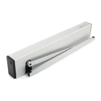
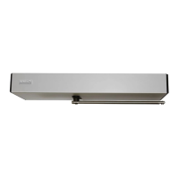
Provides an overview of the FD 10 drive mechanism and its components.
Explains the normal motorized operation and function during mains failure.
Describes how two FD 10 units work together in bi-parting installations.
Lists technical specifications, application limits according to EN 16005, and rating plate info.
Provides essential recommendations and warnings before starting the mounting process.
Explains the different mounting configurations and orientation of the drive mechanism.
Details the steps for mounting the drive mechanism, including drilling and fixing.
Provides specific instructions and dimensions for mounting with normal rods in lintel configurations.
Offers instructions and dimensions for mounting with sliding rods in pushing and pulling configurations.
Details the procedure for setting the internal stop piece for the desired opening angle.
Explains how to adjust the spring tension for proper closing force.
Describes how to adjust the acceleration for reliable door lock engagement.
Covers safety precautions and requirements for connecting the main power supply.
Advises on correctly routing cables between the drive module and chassis profile.
Guides on mounting and connecting external control and safety elements.
Explains the function of the switch and lists available operating modes.
Details how to navigate menus and change settings using the display and joystick.
Outlines the steps for initial setup, including switching on and basic programming.
Describes adjustable parameters like speeds, delays, forces, and opening angles.
Details configurable functions such as safety element settings and relay outputs.
Explains settings for synchronized operation and interlock functions between two doors.
Illustrates the menu structure for navigating and adjusting parameters and configurations.
Defines the order of opening and closing for bi-parting door leaves.
Describes how to set up interlock functions between two doors for secure access.
Details the placement of service, arrow, glass, and rating plate stickers.
Provides instructions for attaching the drive mechanism's protective covering.
Emphasizes the importance of regular maintenance and checking by an expert.
Presents a checklist for the regular service and maintenance of pedestrian doors.
Outlines basic checks and procedures for the fundamental servicing of the drive mechanism.
Explains how to interpret error codes displayed by the control unit.
Lists common malfunctions related to the drive mechanism and operation.
Covers issues with safety elements, power supply, system faults, options, and interlocks.
Provides guidance for resolving issues not indicated by error codes.
Details preparation, procedure, LED indicators, and error resolution for USB software updates.
Provides instructions for de-commissioning the installation and environmentally responsible disposal.
Lists article numbers and designations for available spare parts.
Introduces D-BEDIX, its keys, symbols, modes, menus, and settings.
Introduces KOMBI-D-BEDIX, connection plates, and continuous covering.
Guides on commissioning relay PCBs and the function/mounting of safety sensors.
Details the mounting and use of the LZR-FLATSCAN safety sensor.
Lists additional documents, such as wiring diagrams.
| Category | Door Opening System |
|---|---|
| Model | FD 10 |
| Max. door weight (double leaf) | 2 x 80 kg |
| Protection class | IP20 |
| Max. door weight (single leaf) | 100 kg |
| Power supply | 230 V, 50 Hz |
| Opening Width | Unknown |
| Opening Height | Unknown |
| Motor Power | Unknown |
| Weight | Unknown |