Push back the plastic terminal cap to reveal the eyelet connector on the end
of the wire. Align the eyelet with the hole in the terminal you are currently
working on. Screw in one of the terminal bolts (each includes one washer
and 1 spring washer) and secure. Push the cap back into place.
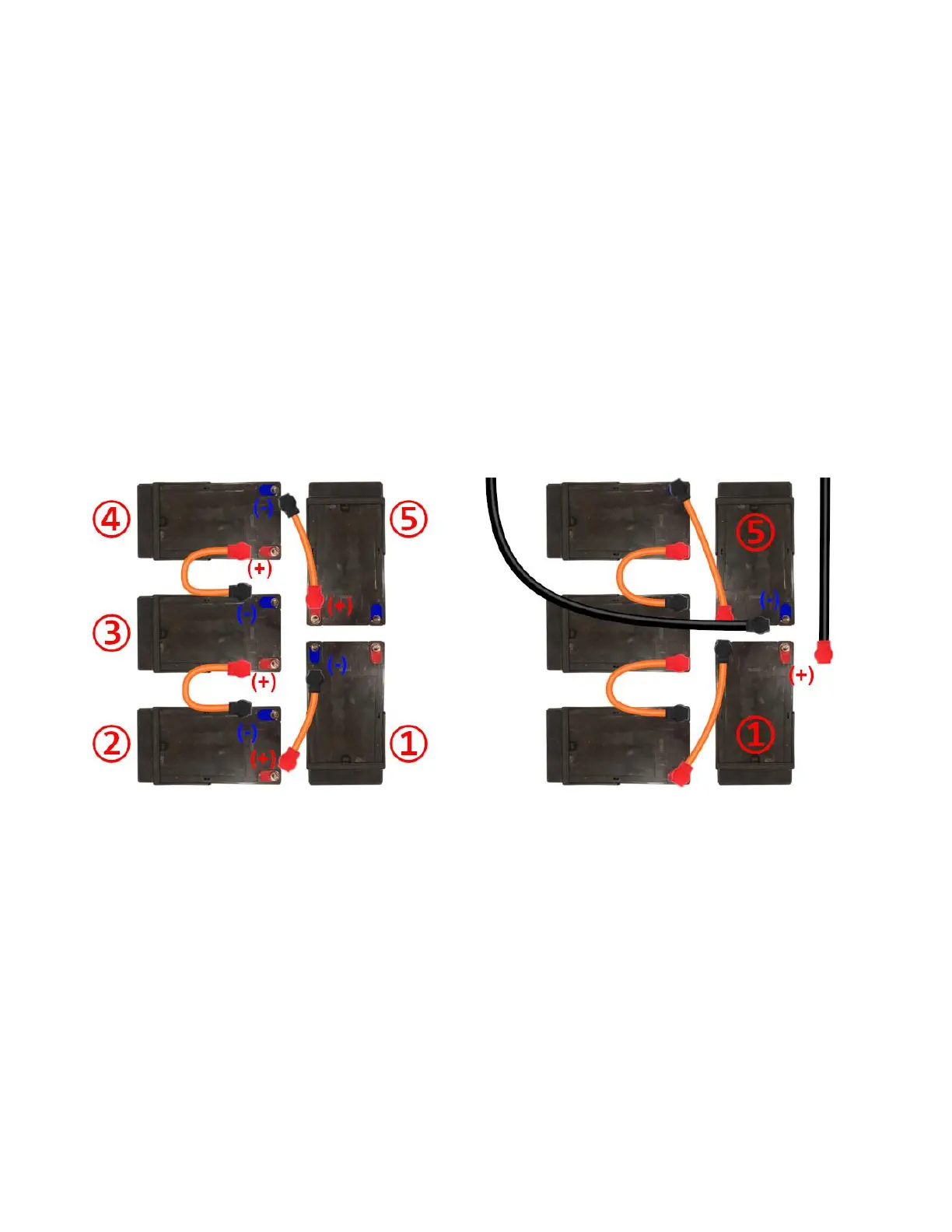
Beginning with battery #1, connect a battery wire to the blue negative (-)
terminal. Color coordinate the terminal cap with the color of the terminal
itself to ensure the right connections are made. (Blue and Black both
representing negative (-) ) Next connect the other end of the battery wire to
the red positive (+) terminal on battery #2. Repeat the process in order so
the following connections are made: Battery 1 (-) → Battery 2 (+), Battery 2
(-) → Battery 3 (+), Battery 3 (-) → Battery 4 (+), Battery 4 (-) → Battery 5 (+)
Once the 5 batteries are connected in series you can locate the red (+) and
the black (-) battery leads coming from up from below the seat back which
are connected to your controller and charging port located in the
compartment behind the access panel in the seat back.
Connect the (-) lead to the (-) terminal on battery #5 and the (+) lead to the
(+) terminal on battery #1 in the same manner as the previous connections.
The batteries are now connected, flip the breaker to the on position and
power up the scooter to test to see if they are properly connected. Provided
proper function, power off the scooter and flip the breaker back to off and
finish the rest of the assembly process.
08