1.
R_Std
or R_Hi indicates Standard or High Sensitivity Range correspondingly
.
2. Battery indicator shows the battery state in 3 levels.
Battery level 3: Full charge (more than 50%).
Battery level 2: Low charge (20 - 30%).
Battery level 1: Very low charge. Battery charging is required (remaining battery working
time is about 10 min).
3. LCD leak indicator. When gas leak is detected, bar graph is displayed. The number of
displayed bars in the graph indicates level of gas leak.
Zero Point (no leak):
1st bar on the left end is blinking.
Gas Leak:
■
- black bars indicate the gas leak for a gas, which has higher thermal
conductivity than air (He, H, etc.).
□
- blank bars indicate the gas leak for a gas, which has lower thermal conductivity than
air(Ar, CO
2
, etc.).
4. LED leak indicator. When a gas leak is detected, total number of LED lights lit to the left
and right of the LCD display (max. 8 LED’s) indicates the size of the leak. LED leak indicator
can be used in addition to the LCD display indicator. The LED indicator can be enabled or
disabled via the configuration settings (refer to chapter 6 “Setting Configuration
Parameters”).
Zero Point (no leak): green or red LED blinks when the detector becomes stable at around
zero point.
Gas Leak: Red LED lights indicate the gas leak for a gas, which has higher thermal
conductivity than air (He, H, etc.). Green LED lights indicate the gas leak for a gas, which
has lower thermal conductivity than air (Ar, CO
2
, etc.).
Operating Procedure
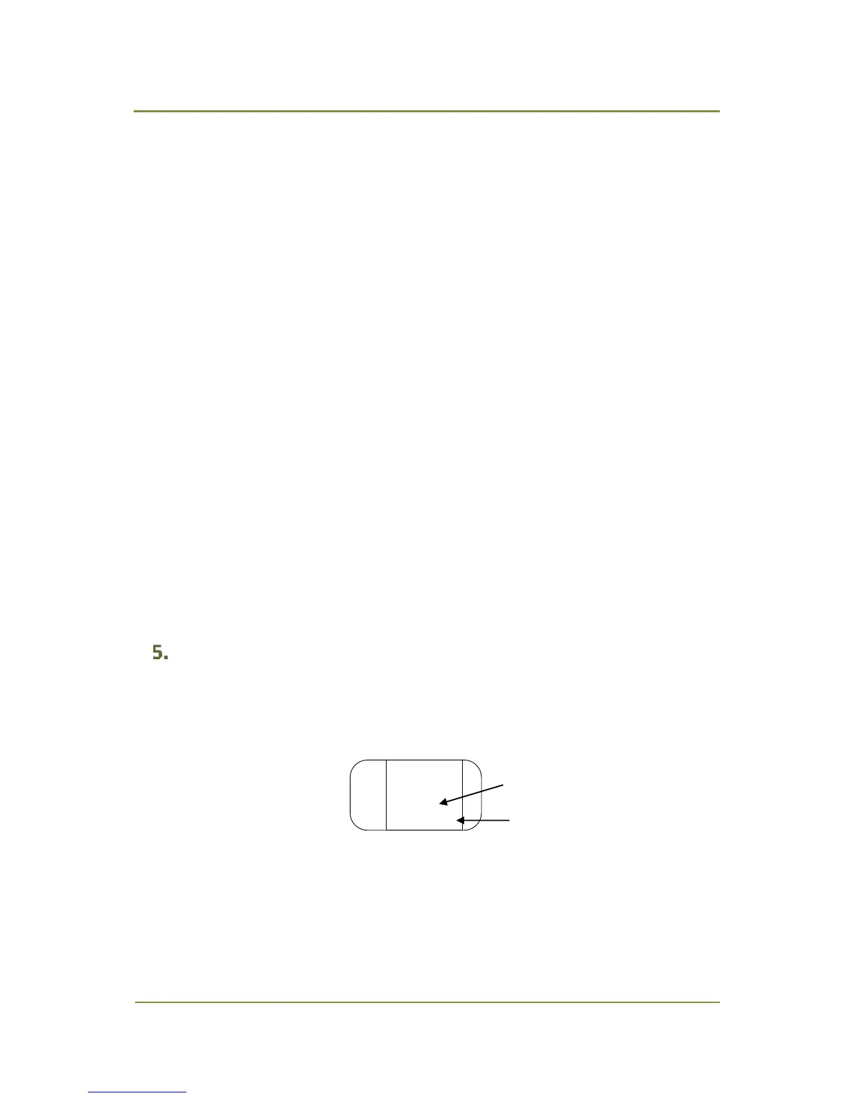
1. Press FUNC/POWER key for about 1 sec to turn power on. LCD will show warming-up display
(Fig. 5.1). Warming-up takes approx. 25 sec at standard (Std) and approx. 90 sec at high (Hi)
sensitivity range setting.
2.
Fig. 5.1 Warming Up Display, Standard Range
After warming up, a standard display is shown (Fig. 4.1).
3. Check the detector stability at zero point. First bar on the left will be blinking black or blank
alternately when the detector is in stable condition. Periodically, the detector needs to be