- 8 -
Installation Instruction
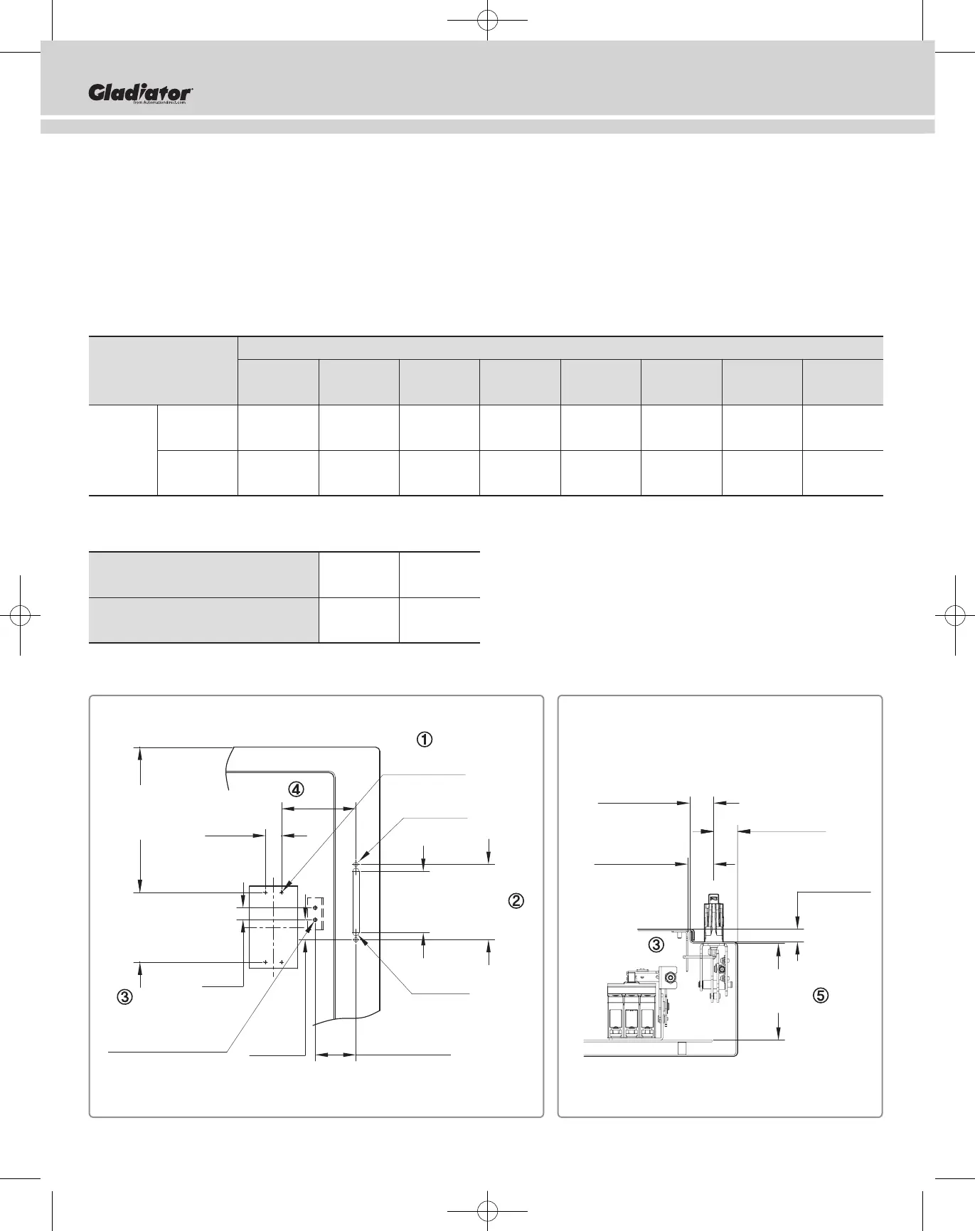
2. Medida del Tap & Hole necesaria para instalar el COM and Flange Handle
① Prepare 4 lugares del Tap 6-32UNC para adherir COM.
② Prepare para adherir the Flange Handle Assembly.
③ Prepare 2 lugares de Bolt Stud 1/4-20UNC para adherir Lock a Door.
④ El lugar de instalación puede cambiar dependiendo de Cable Extension.
Cable Extension: 60/72 pulg (1524.0/1828.8 mm)
⑤ Enclosure Depth “D” debe ser mínimo 8.66 pulg (220.0 mm).
※ Maximum Measure to Install COM
[Unidad: pulg (mm)]
Medida del lugar de Enclosure Depth
instalación 10 12 16 18 20 24 30 36
“E” max (254.0) (304.8) (406.4) (457.2) (508.0) (609.6) (762.0) (914.4)
60 25 24 23 22 21 20 19 18
Cable (1524.0) (635.0) (609.6) (584.2) (558.8) (533.4) (508.0) (482.6) (457.2)
Lengths 72 30 29 28 27 26 25 24 23
(1828.8) (762.0) (736.6) (711.2) (685.8) (660.4) (635.0) (609.6) (584.2)
※ Medida mínima para Enclosure “D”
[Unidad: pulg (mm)]
Medida estándar “E” para instalar COM
0~1.77 1.77~
(0~45.0) (45.0~)
Enclosure Depth “D” Mín
8.86 4.72
(225.0) (119.9)
4-(6-32UNC)
0.75
[19]
0.98
[25]
4.33
[110]
3.82
[97]
4.69
[119]
MIN 4.72
[120]
E
2-(1/4-20UNC)
STUD BOLT
R0.2
[R5]
MAX 2.52
[64]
1.24
[31.4]
2-Ø 0.26
[2-Ø 6.6]
MIN<1.18>
[30]
MAX<0.79>
[20]
MAX<2.01>
[51]
MAX<1.89>
[45]
MIN<8.66>
[220.0]
"D"
 Loading...