2
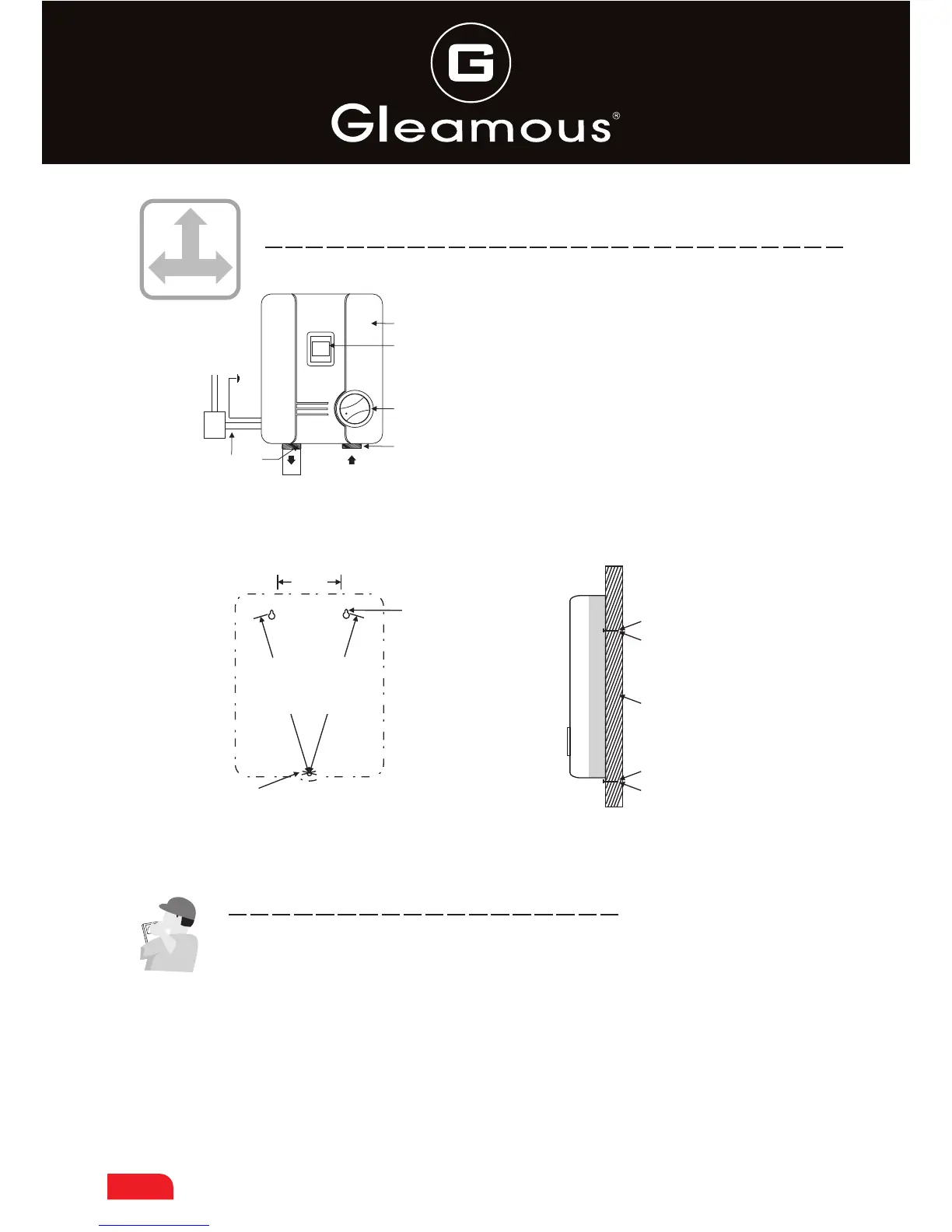
IV. Part Designation and Installation Diagram
88
1
2
6
3
DSK-45EP
4
N L E
5
LEAKAGE
PROTEATION
SWITCH
1. Mains Pressure Cold Water Inlet
2. Adjustable Temperature Setting
3. Safety Cover
4. Hot Water Supply Outlet
5. 15 AMP power cable
6. Digital Temperature display
Fig2
¢8mm x 25mm
Expansion Bolt
Masonary Wall or
Plaster board
¢8mm x 25mm
Expansion Bolt
10cm
2
4
cm
2
4
cm
10
Fixing Holes for fixed water Heater
V. Installation procedure
1. The unit must only be installed by a licenced Electrical Contractor.
2. A earth leakage circuit breaker with 30mA is required to install for the
circuit controlling this unit.
3. The electric water heater should be wall-mounted installed. First
determine the right position for installation of the unit (See fig 2). Mark
& drill three holes(8mmx25), insert the expansion bolt on the top, keep
Fig1
Installation diagram
Installation diagram of DSK-45EP

 Loading...