Supplied By www.heating spares.co Tel. 0161 620 6677
Page 19
ELECTRAMATE
2000
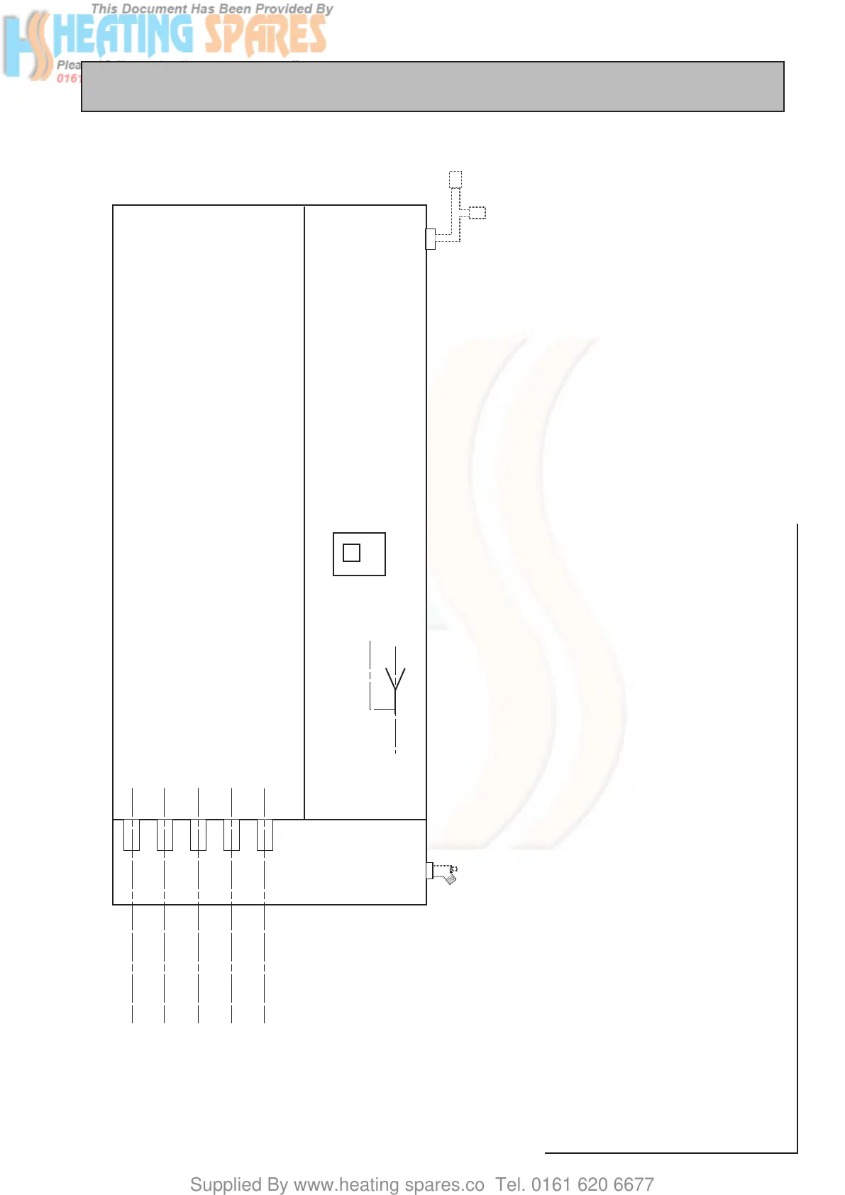
The position of the pipework connections is
shown opposite. The connection sizes and
dimensions are listed in Section 1.2 Technical
Data.
All the connections are also labelled on the
appliance. It is essential that the pipework is
connected to the correct connection.
The connections can be hard piped but we
recommend the use of flexible connections
(available as an optional extra).
Connections A, B, C, D, E and F are plain ended
copper pipe.
Connection G is a compression fitting.
Connection H is RC½ (½ in BSPT internal).
A - Domestic Hot Water
B - Central Heating Flow
C - Incoming Mains Cold Water
D - Central Heating Return
E - Expansion Pipe
F - CA Valve/PRV Discharge Pipe
G - AAV/AVV Assembly
H - Drain Valve NOT provided with the
appliance).
All factory made joints should be checked after
installation in case they have been loosened
during transit.
The expansion pipe should be run from the
appliance and connected to the inlet pipe/air
vent provided with the expansion vessel.
There must be no isolating valve between
the expansion vessel(s) and the appliance.
Run the discharge pipe from the CA Valve/
PRV to a position where the termination is
visible and will not cause danger to persons or
damage to materials - see 1.3 System Details
for further information.
2.0 INSTALLATION
2.2 INSTALLATION
Pipework connections