8.0 FLUE OPTIONS
8.1 CONCENTRIC AIR/FLUE DUCT SPECIFICATIONS
The Dimplex Combi 24, Dimplex Combi 30 and Dimplex Combi
38 can be installed to a number of different concentric flue
systems. The different flue applications as shown in Fig. 20 are
available as kits comprising the connecting parts to the
appliance and end terminal. Flue extension ducts and extension
elbows are available as accessories.
Dimplex Combi 38 only, with maximum concentric
flue length of 10m, the heat input will be reduced by 6.1%
8.2 Kit A + Telescopic Horizontal Wall Terminal
(C13) - Part No. 956120
Traditional concentric flue system, Fig. 21, with a maximum
length of 10000mm. The flanged flue elbow is designed with a
3° slope towards the appliance so that the condensate can
easily drain off. It has to be considered that for every metre
horizontal flue length the terminal exit centreline is approx.
45 mm higher than the elbow’s centreline.
The standard telescopic terminal is 615mm max length and
430mm min length, but can be cut to a minimum flue length of
250mm, which is suitable for single, 100mm (4”), brick walls.
8.3 Kit B Vertical Concentric Flue Terminal
(C33) - HBL Part 956081
Standard concentric (100/60) vertical flue application, Fig. 22,
through roof attics with a maximum length of 12000mm.
The kit comprises of the roof terminal, flashing kit, vertical
adaptor with sampling point and bracket.
The maximum length is measured from the top of the
appliance casing to the underside of the air cowl.
For installation details refer to the flue kit instructions.
Chimney flue liner kit
- Part no. 956082
Vertical flue kit - Part no. 956081
Vertical flue kit - Part no. 956081
with flat roof flashing plate
Split pipe vertical flue outlet kit
- Part no. 956080
with flat roof flashing plate
Raised external flue outlet kit
- Part no. 956084
Vertical flue kit - Part no. 956081
External vertical flue kit
- Part no. 956085
Standard telescopic
horizontal flue kit
- Part no. 956120
Flue system application
The pluming from the flue may
cause nuisance to neighbours
or other buildings.
60/100 flue accessories:
0.5m flue extension duct - 956092
1m flue extension duct - 956093
93 flue extension elbow - 956091
45 flue extension elbow (2x) - 956090
Vertical flue turret - 956087
Ø60/100mm concentric
standard horizontal wall
terminal.
Max. length 10,000mm.
Min. length 250mm.
Standard telescopic horizontal flue kit - Part no. 956120
Horizontal terminal has a
built-in fall in the flue to allow
condensate to drain away.
If horizontal flue requires
extension pipe. the flue
should be installed such
that there is no section less than
2.5° - 3° to the horizontal,
falling back towards the boiler.
93 flanged elbow (concentric)
with sampling point
Kit A +
Vertical flue kit - Part no. 956081
Suitable for 25 - 45°
Pitch Angle
Length
Kit B
60/100 flue accessories:
0.5m flue extension duct - 956092
1m flue extension duct - 956093
93 flue extension elbow - 956091
45 flue extension elbow (2x) - 956090
Flat roof flashing plate - 840512
93 flanged flue elbow - 956086
Max. length12m.
Min. length 0.6m.
Roof terminal
with rain cover
and pitched roof
flashing kit.
Vertical flue socket
with sampling point.
Top of Boiler
to underside of Cowl
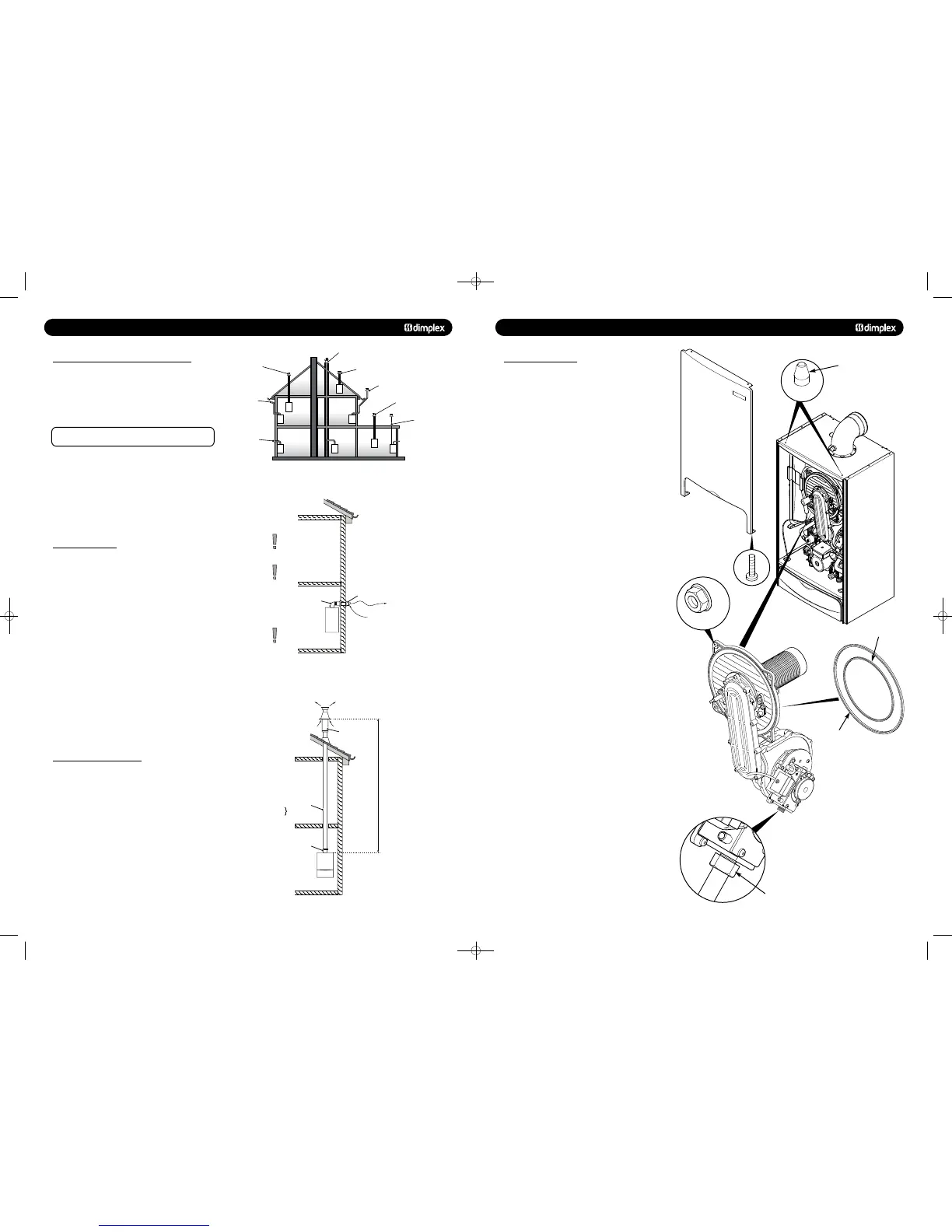
12.0 SERVICING AND MAINTENANCE
12.1 ANNUAL SERVICING
8. Remove the two screws securing the front panel to the
underside of the boiler. Lift the panel upwards off its retaining
studs on top of the appliance.
9. Disconnect the two leads to the fan and one lead to the gas
valve.
10. Undo the nut on the gas inlet pipe to the valve and retain
the sealing washer.
11. Remove the four nuts holding the burner door plate and
remove the valve and fan assembly (Fig. 51).
12. Clean any debris from the heat exchanger using a soft
brush and check that the gaps between the tubes are clear.
13. Inspect the burner, electrode positions and insulation,
cleaning or replacing if necessary.
14. Check the condition of the burner door seals, replacing if
necessary.
15. Reassemble in reverse order.
16. Complete the relevant Service Interval Record section of
the Benchmark Commissioning Checklist at the rear of this
publication and then hand it back to the user.
© Dimplex Boilers 2008
Fig. 51
Fig. 49
Fig. 50
Fig. 52
Gas Inlet Nut
Front Panel
Retaining Stud
Burner Door Seal
Inner Seal
48pp MANUAL SPREADS 19/10/10 08:36 Page 18
 Loading...

