1. With a demand for heating, the pump, circulates water
through the primary circuit.
2. Once the main burner ignites the fan speed controls the gas
rate to maintain the heating temperature measured by the
temperature sensors.
3. When the demand is satisfied the burner is extinguished and
a 5 minute delay occurs before the burner will re-light (anti-
cycling), the pump continues to run for a period of 2 minutes
(Pump Overrun).
1. Priority is given to the domestic hot water supply. A demand at a
tap or shower will override any central heating requirement.
2. The flow of water will operate the Flow Turbine which requests the
3 way valve to change position. This will allow the pump to circulate
the primary water through the DHW plate heat exchanger.
3. The burner will light automatically and the temperature of the
domestic hot water is controlled by the temperature sensors.
4. When the domestic hot water demand ceases the burner will
extinguish and the diverter valve will remain in the domestic hot water
mode, unless there is demand for central heating.
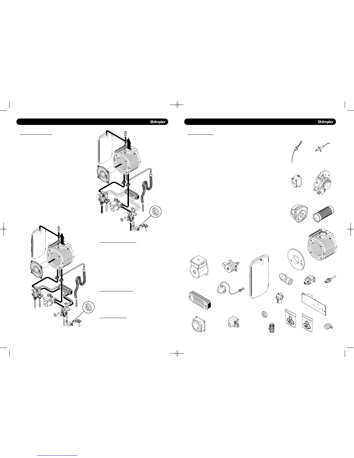
1 H29-740 Electrode - Ignition c/w Gasket 1 988526
2 H38-213 Detection Electrode c/w Gasket 1 988540
3 H29-236 Spark Generator c/w Lead 1 500665
4a TBA Dimplex Combi 24 gas control valve assembly NG 1 988660
4b TBA Dimplex Combi 30 gas control valve assembly NG 1 988661
4c TBA Dimplex Combi 38 gas control valve assembly NG 1 988662
5 H38-215 Fan Assembly 1 601016
6a H29-171 Burner (Combi 24) 1 700600
6b H29-172 Burner (Combi 30) 1 700601
6c TBA Burner (Combi 30) 1 700602
7 TBA Burner Door Insulation 1 352671
8a H38-217 Heat Exchanger (Combi 24) 1 451101
8b H38-218 Heat Exchanger (Combi 30) 1 451100
8c TBA Heat Exchanger (Combi 38) 1 451151
9 H29-202 Pump Head 6m 1 500672
10 H29-203 Diverter valve Motorised Head 1 500750
11 H29-237 Expansion Vessel 1 451020
12 TBA 3 Bar Pressure Relief valve 1 500751
13 H29-213 Water Temperature sensor 2 500661
14 H38-219 Flue Thermistor 1 500662
15a TBA Dimplex Combi 24kW Plate Heat exchanger kit 1 988671
15b TBA Dimplex Combi 30kW Plate Heat exchanger kit 1 988672
15c TBA Dimplex Combi 38kW Plate Heat exchanger kit 1 988673
16 E23-541 Pressure Gauge 4bar 1 450961
17 TBA Auto Air Vent 1 500752
18a TBA Dimplex Combi 24 NG PCB Kit 1 988663
18b TBA Dimplex Combi 30 NG PCB Kit 1 988664
18c TBA Dimplex Combi 38 NG PCB Kit 1 988665
19 E23-671 Time Clock - Grasslin FM1STUH 1 600520
20 TBA DHW Flow Turbine 1 300766
21a TBA DHW Flow Regulator (Combi 24) 1 300717
21b TBA DHW Flow Regulator (Combi 30) 1 300715
21c TBA DHW Flow Regulator (Combi 35) 1 300719
22 H29-179 Valve - Manual Bleed 1 300730
23 H38-226 Heat Exchanger seal & Clip Kit 1 988546
24 H29-208 Hydroblock - O-Ring and Clip 1 988669
25 TBA Hydroblock Manual bleed cock 1 500708
1
2
3
4
5
6
8
7
12
13
14
11
10
16
9
15
19
20
21
22
17
23
24
25
18
48pp MANUAL SPREADS 19/10/10 08:36 Page 8
 Loading...

