Glentek Inc. 208 Standard Street, El Segundo, California 90245, U.S.A. (310) 322
SMA7130, SMA71075 and SMA71100 MANUAL
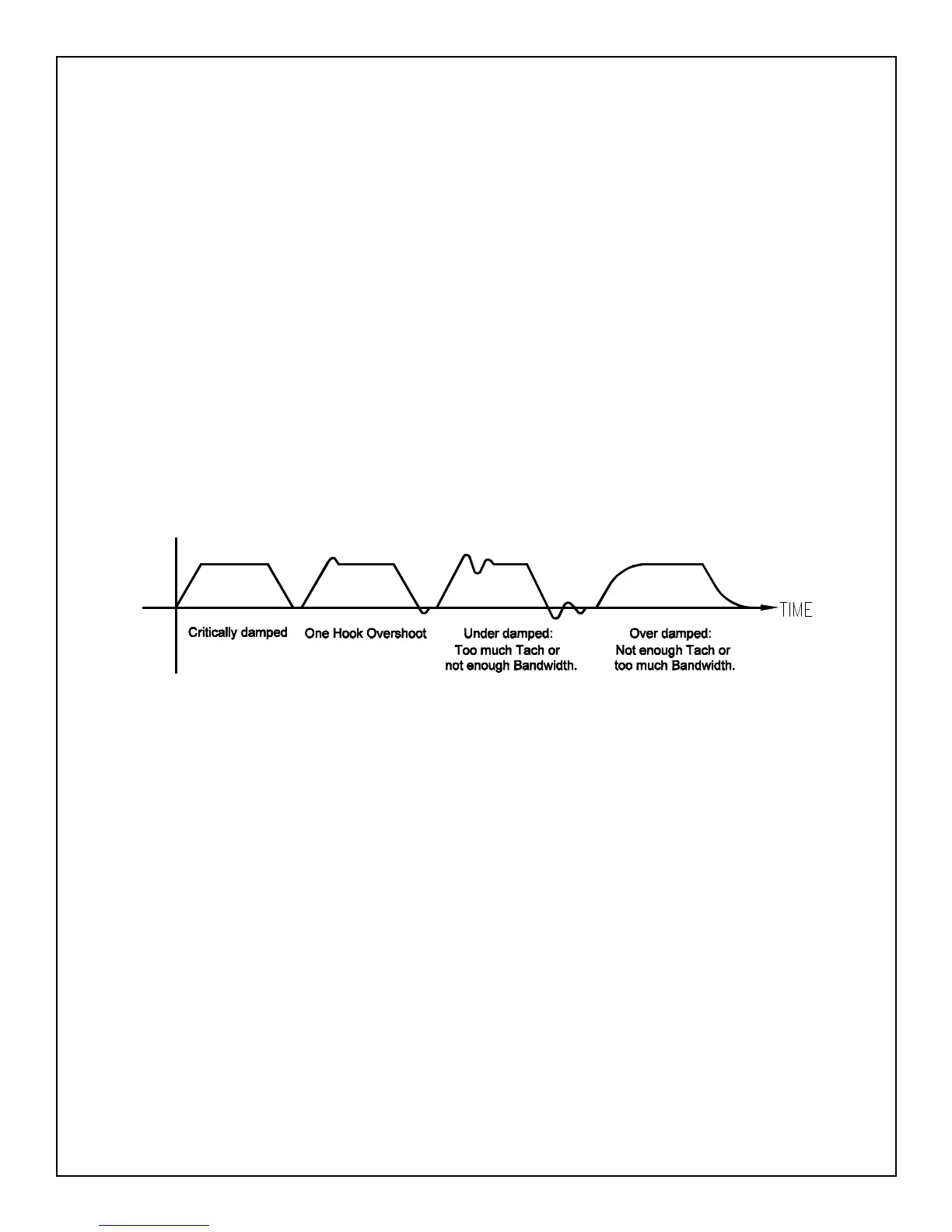
Figure 6.1
Critically damped, One Hook Overshoot,
Under and Over damped waveforms
PROCEDURE:
1. Apply the main power and fan power.
2. Slowly turn the Loop Gain pot (RV7) CW. The motor should be stopped or turning slowly. If the motor starts
running away, remove the power, reverse the tach leads, and retest.
3. Set the Balance pot (RV4) for zero motor rotation.
4. Connect an oscilloscope to J1-7 (ABS I) and a battery box to J1-3 (J1-4 is common for both). The voltage on J1-
7 is a function of motor current (See section 4.3.4.2). While applying a step input voltage, adjust the Current
Limit pot (RV6) for the desired peak current.
The purpose of the following procedure is to set the system bandwidth to obtain a critically-damped response or
a one hook overshoot response with the maximum possible Tach. Gain. There are many possible settings of
Tach. Gain and Compensation which will yield the desired waveform. The optimum setting will occur when Tach
Gain is as CW as possible and Compensation is as CCW as possible. However, the servo loop may become
unstable (the motor oscillates or hunts) with a very low (near CCW) setting of Compensation. In this case,
stability is the limiting factor. At no time should the servo-loop be allowed to be unstable.
Amplifiers are normally shipped with the Tach. Gain pot (RV3) set at 100%. This is a good place to start. If you
are unsure of where the Tach. Gain is set, turn the Tach Gain (RV3) fully CW (up to 20 turns).
5. Connect an oscilloscope to J1-5 (TACH IN) and J1-4, common. Set the battery box for a DC signal output to
obtain approximately 400RPM. The RPM may be set by measuring the tach voltage at J1-5, e.g., 2.8VDC for a
7V/KRPM tach is 400RPM.
6. Pulse the input and compare the waveform with figure 6.1.
7. Adjust the Compensation pot (RV5) CCW until the waveform is critically damped or one hook overshoot. Then
proceed to step 9.
8. If the desired waveform cannot be obtained by adjusting the Compensation pot, back off (CCW) the Tach Gain
pot (RV3) a few turns and repeat step 7.
9. Do not adjust the Tach Gain or Compensation pots for the rest of the calibration procedure.
10. With the battery box still connected at J1-3 and J1-4 for single-ended input (or if your system uses the
Differential input, move battery box to J1-1 and J1-2), set the battery box for a known DC voltage. Adjust the
Signal Gain pot (RV2) or (RV1 for differential input) to obtain the desired motor velocity.
11. If the motor is rotating in the wrong direction for a given input polarity, remove power and reverse both the motor
leads and the tach leads.
12. Remove the battery box, and repeat step 3.
13. Calibration complete. Reconnect signal wires.
CHAPTER 5: CONFIGURATION


 To Next Page