Glentek Inc. 208 Standard Street, El Segundo, California 90245, U.S.A. (310) 322
SMA7130, SMA71075 and SMA71100 MANUAL
Chapter Two: Theory of Operation
2.1 Introduction:
This chapter contains the basic control theory of how brush type and brushless servo motors and amplifiers
operate. It also compares and contrasts the advantages and disadvantages of brushless and brush type motors
and amplifiers to help you select which is best suited for your application. The following is a summary of the
topics:
• The theory behind an amplifier driving DC servo motors.
• A comparison between brush type and brushless motors.
• Operation of output switching transistors.
• “H Type” output bridge configuration.
• Pulse-Width-Modulation (PWM).
• Current-Loop and Velocity-Loop operation.
• Protection circuits.
2.2 Driving DC Servo-Motors:
The torque of any DC motor is proportional to motor current: the stronger the magnetic field, the stronger the
pull. Motor current may be controlled in two ways: linear and PWM (Pulse-Width Modulation). Linear control is
achieved by simply inserting a resistance in series with the motor. This resistance is usually a partially turned on
transistor. The transistor is said to be in its "linear" region. Linear amplifiers are simple, accurate, and effective.
However, they are very inefficient and they generate a lot of heat. Linear amplifiers are used when low electrical
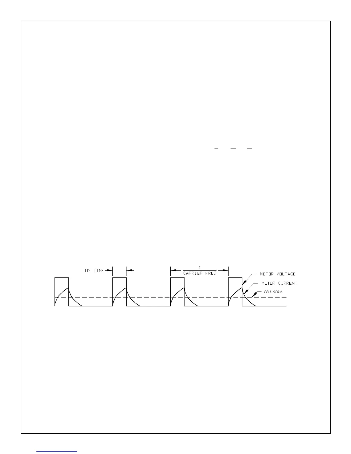
noise, high bandwidths (2KHz or higher) and or low inductance (less than 1mH) motors are used. In pulse-width
modulation the control devices (output transistors) are rapidly turned full on and full off. The ratio of the on time
(the pulse width) and off time determines the average motor current. Refer to figure 2.1. For example: if the
output is on 25% of the time and off 75% of the time, the average motor current is approximately 25% of
maximum.
A coil of wire, such as the windings of a motor, forms an inductor. Inductors resist changes in current. This
resistance to change, known as reactance, acts to dampen or average the high-current spikes that would
otherwise occur when the output devices are on. In fact, if motor inductance is low, external inductors may have
to be added in series with each motor lead to ensure proper operation.
A brush type motor may be run from a steady DC voltage since the brushes and commutator switch the
current from winding to winding. However, a brushless motor requires that the voltage be switched from winding
to winding externally; the voltage that drives a brushless motor is a constantly changing AC waveform. Section
2.5 discusses these waveforms.
Figure 2.1
Pulse Width Modulation Waveform
CHAPTER 2: THEORY OF OPERATION
 Loading...