31
4000123942-2
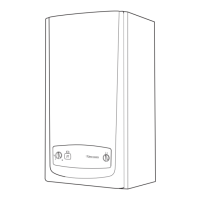
15.3 Front panel
• Unscrew and remove the two retaining screws from the
bottom of the front panel.
• Remove front panel by lifting up and forward.
15.4 Control panel
• Lower forwards to gain access to lower part of boiler.
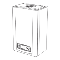
15.5 Sealed chamber cover
• Unscrew and remove the two retaining screws from the
sealed chamber cover, see diagram. 15.3.
• Lift cover up and off pins on top of boiler.
15.6 Side panels (for ease of access if
available), refer to diagram 15.4
• Unscrew and remove the two retaining screws from front of
each side panel.
• Left hand side panel only disconnect the control panel
retaining strap at the control panel.
• Unhook each panel from the front retaining tabs.
• Pull each panel forward from the rear retaining tabs to
remove.
15.7 Combustion chamber cover
• Unscrew and remove the two screws securing combustion
chamber cover to combustion chamber, see diagram 15.5.
• Remove combustion chamber cover from boiler.
15.8 Ignition and Flame Sensing Gaps
• Check that the ignition and flame sensing gaps as shown in
diagram 15.6. Note: To gain access to ignition and sense
electrodes for removal, refer to Section, 18.11 and 18.12 in
Replacement of Parts.
15.9 Burner, refer to diagram 15.7
• Unscrew and remove the two burner retaining screws.
• Remove burner from boiler by easing it forward off the two
burner guides, taking care not to damage the insulation.
• Clean burner by washing in soapy water. Dry thoroughly
before refitting.
Note: To gain access to injectors for removal and cleaning,
refer to Section, 18.8.
15.10 Fan, refer to diagram 15.8
• Disconnect power supply leads and earth lead from fan.
• Unscrew and remove the two fan retaining bolts.
• Ease the fan down and forwards to remove.
15 Routine Cleaning and Inspection
Diagram 15.3
9533
Diagram 15.4
9797
97999800
24ci shown
 Loading...
