47
4000123923-2
9646
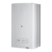
Diagram 20.3
SENSING
TUBE
AIR PRESSURE
SWITCH
20 Replacement of Parts
ELECTRICAL
CONNECTORS
RETAINING
CLIPS
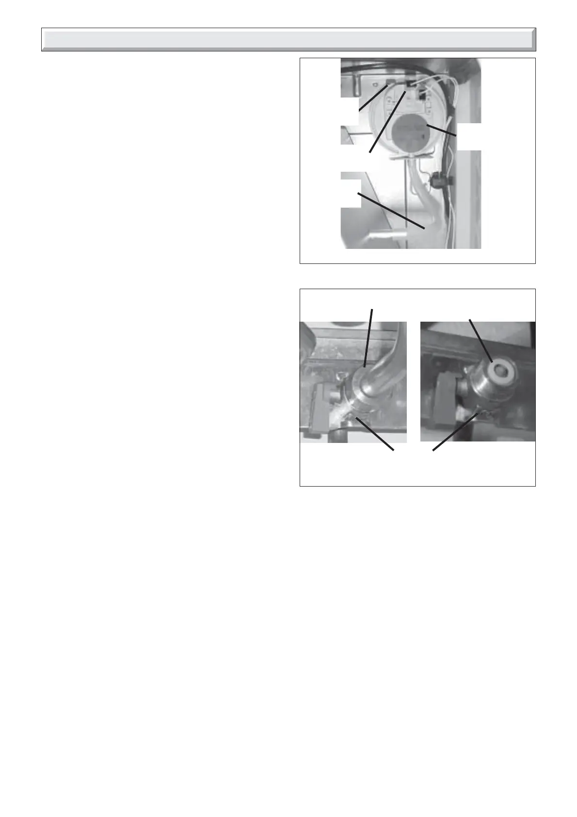
Diagram 20.4
COLD WATER INLET
RESTRICTOR
COLD WATER IN
ISOLATING VALVE
UNION NUT
11932
11939
30ci Only
20.2 Fan, refer to Section 17.10.
Before starting refer to the front of Section 20 Important
information.
• Remove the front panel, refer to Section 17.3.
• Remove the sealed chamber cover, refer to Section 17.5.
• Remove the fan, refer to Section 17.10.
20.3 Air pressure switch
Before starting refer to the front of Section 20 Important
information.
• Remove the front panel, refer to Section 17.3.
• Remove the sealed chamber cover, refer to Section 17.5.
• Locate air pressure switch situated at the top right hand
side, see diagram 20.3.
• Remove air pressure switch tube from sensing probe on flue
hood.
Note: Do not fit tube until the air pressure switch is in position.
• Disconnect air pressure switch electrical connections.
• Unclip to remove air pressure switch.
20.4 (30ci Only) Domestic water inlet filter
If the water flow rate through the appliance has reduced it may
be necessary to clean or replace the water inlet filter.
Before starting refer to the front of Section 20 Important
information.
• Remove the front panel, refer to Section 17.3.
• Lower the control panel, refer to Section 17.4.
• Clean or replace the water inlet filter, refer to section 17.12.
20.5 Central Heating Filter
It may be necessary to clean or replace the central heating
filter.
Before starting refer to the front of Section 20 Important
information.
• Clean or replace the central heating filter, refer to section
17.13.
20.6 (30ci Only) Cold water inlet restrictor
Before starting refer to the front of Section 20 Important
information.
• Remove the front panel, refer to Section 17.3.
• Lower the control panel, refer to Section 17.4.
Drain down domestic hot water circuit of boiler only, refer to
relevant part of diagram 20.1.
• Remove the retaining wire.
• Undo union nuts from boiler cold water in isolating valve.
• Clean and inspect restrictor, replace if necessary, see
diagram 20.4.
20.7 Burner, refer to Section 17.9.
Before starting refer to the front of Section 20 Important
information.
• Remove the front panel, refer to Section 17.3.
• Lower the control panel, refer to Section 17.4.
• Remove the sealed chamber cover, refer to Section 17.5.
• Remove the combustion chamber cover, refer to Section
17.7.
• Remove the burner, refer to Section 17.9.
20.8 Burner injectors, refer to diagram 20.5.
Before starting refer to the front of Section 20 Important
information.
• Remove the front panel, refer to Section 17.3.
• Lower the control panel, refer to Section 17.4.
• Remove the sealed chamber cover, refer to Section 17.5.
• Remove the combustion chamber cover, refer to Section
17.7.
• Remove burner from boiler, refer to Section 17.9.
• Remove and replace injectors as required.
Note: The injectors may be cleaned, remove injectors inspect
and clean. Do not use a wire or sharp implement.
Note: Make sure that injector size, marked on each injector, is
the same as that given in ‘Section 1 Technical Data’ for the
type of gas being used.
 Loading...

