0020096321_01 - 02/11 - Glow-worm
- 7 -
Key
1 Heat pump controlled by On/Off contact
2 Heat pump circuit fi lter (not supplied)
3 Hydraulic module
4 Electrical power and protection of the heat pump
5 Electrical power and protection of the module
6 Heat pump control unit
7 Wireless outdoor sensor
8 Systempro control unit
9 Climapro2 RF programmable wireless room thermostat
10 Heating circuit
11 Overheating safety (UFH shown, but can be underfl oor or radiators)
12 Glycol PRV discharge
A Heating circuit return
B Heating circuit fl ow
C Heat pump circuit safety valve discharge
D Heat pump circuit fl ow
E Heat pump circuit return
Application conditions
- The Systempro control unit manages the operation of the
boiler, the heat pump and the module.
- The Systempro control unit manages up to 3 heating zones.
- The heat pump command unit is used as a setting or
diagnostic tool.
- Each wireless room thermostat can control a heating zone.
- The installation can be performed with a low-temperature
heated fl oor (heating outlet temperature < 50°C) or low
temperature radiators (heating outlet temperature < 70°C).
- The overheating safety device must be connected to the
hydraulic module pump power supply.
e
Use 0.75 mm² section cables for the electrical
connections to the control unit.
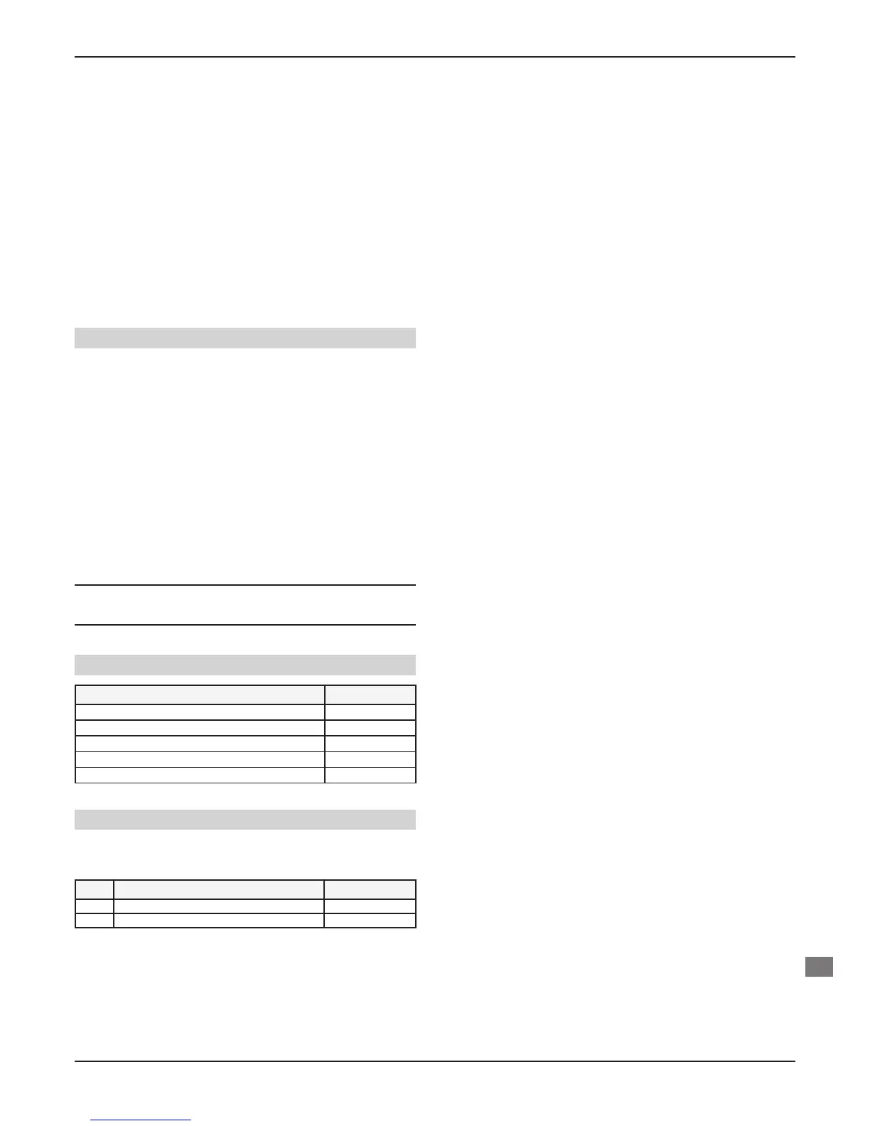
Control unit settings
Description of main settings Setting
Diagram no. 7
Did you install a multizone kit ? No
Heating curves
0.1 - 1.5
Max. heating fl ow temperature 30°C < T < 70°C
Heat pump external shutdown temperature -20°C < T < 20°C
Heat pump control unit settings
• Refer to the heat pump installation manual to access the
“After-sales” parameters listed below.
Menu Function name Setting
112 Heating curves (*) 7 - 12
114 ECO heating mode (*) 1 - 20°C
(*) Refer to the correspondence table in the “Settings > Heating”
section.
MAINTENANCE
EN
 Loading...
