22
221132B
1 1 C o m m i s s i o n i n g
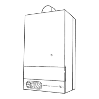
Diagram 11.3
SIT
Diagram 11.2
Diagram 11.3
HONEYWELL
SECURING SCREWS (2)
Slacken but do not remove
CAP
IGNITION
LEAD
PIEZO
UNIT
2932
CAP
SPINDLE
SMALL
ADJUSTMENT
NUT (MAX.
PRESSURE)
2344
AUTOMATIC AIR
VENT CAP
4447 S
TEST
POINT
LARGE
ADJUSTING
NUT (MIN.
PRESSURE)
ELECTRICAL
CONNECTOR
(GREY)
SCREW
PIEZO UNIT
BRACKET
Slide forward
and lower to
release from
keyhole fixing
ELECTRICAL
CONNECTOR
(GREY)
WHITE ADJUSTER
SCREW
(MIN PRESSURE)
LARGE ADJUSTING
NUT (MAX PRESSURE)
TEST
POINT
Make sure that the automatic air vent is operating
correctly, see diagram 11.2.
Take care not to splash any of the electrical components.
Alternate the position of switch “C” between “On” and
“Off” positions to ensure that water flows through all
parts of the boiler and air is not trapped in the boiler
internal bypass.
Pressurise the system until the pressure is 1.5bar
(21.5lbf/in
2
). Check the heating system and boiler for
water soundness.
Check the operation of the safety valve by turning the
safety valve knob in the direction of the arrow.
Lower the pressure to the initial cold fill design pressure,
refer to Section 1.6 “Data”. Position the set pointer on
the boiler pressure gauge at this pressure also.
11.3 Preparation for Lighting
Isolate the boiler from the mains electrical supply at the
external isolator.
Test for soundness and purge air from the gas supply.
Turn on the gas service cock, slot in line with the length
of the cock.
SIT only - Slacken the two piezo unit bracket screws and
remove the bracket, keyhole slot.
Slacken the burner pressure test point screw and connect
a suitable pressure gauge, see diagram 11.3.
 Loading...