29
10.7 Standard Horizontal Flue
Refer to diagram 10.12 for kit contents.
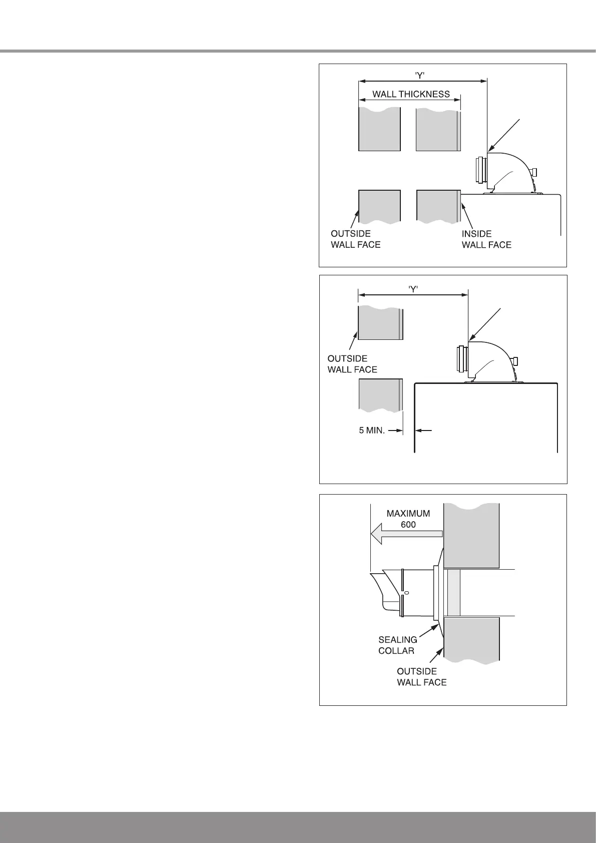
10.8 REAR Flue
With the flue elbow temporarily fitted, measure the distance
from the outside wall to the butt joint, see diagram 10.14. If
the measurement ‘Y’ exceeds 667mm, then the appropriate
length of extension pipe is required. The minimum
dimension is 156mm to suit a 75mm min wall thickness. The
flue can project to a maximum of 600mm, if this is desirable,
refer to diagram 10.16.
10.9 SIDE Flue
With the flue elbow temporarily fitted, measure the distance
from the outside wall to the butt joint, see diagram
10.15. If
the measurement ‘Y’ exceeds 667mm, then the appropriate
length of extension pipe is required. The minimum dimension
for LH is 408mm and RH 195mm to suit a minimum wall
thickness of 75mm. The flue can project to a maximum of
600mm, if this is desirable, refer to diagram 10.16.
10.10 Flue Fitting
Remove the flue elbow.
Separate the flue duct from the terminal by twisting to release
the terminal catch, then pull out of the retaining seal, refer to
diagram 10.17.
The flue duct cutting length (L + 11mm.) is shown in diagram
10.17.
The air duct should be cut at the opposite end to the
terminal
The plastic flue duct MUST be cut at the opposite end to the
terminal catch.
The plastic flue duct extensions MUST be cut at the
opposite end to seal.
The cut ducts must be de-burred and all filings and debris
removed.
Insert the flue duct into the air duct terminal assembly,
remembering to engage the catch within the terminal.
NOTE: If the seals require lubricant to ease installation, do
not use mineral oils or grease, only silicon grease or water is
recommended.
Fit the sealing collar onto the locating ring on the flue
terminal, see diagram 10.8.
Push the flue assembly into the wall, externally or internally,
initially until the end of the assembly protrudes a short way
from the inside face of the wall. This will enable the internal
trim ring (if required) to be positioned and allow the flue
assembly to be drawn back into the flue elbow.
Secure the flue elbow in position on top of the boiler with four
torque headed screws supplied.
13224
Left Hand illustrated
10 Standard Flue - Length, Preparation and Installation
Diagram 10.14
13223
12979
Diagram 10.15
Diagram 10.16

 Loading...


