60
RETAINING
BRACKET
INSIDE VIEW OF
CONTROL BOX
ELECTRICAL
CONNECTION
RETAINING
CLIP
UNION
NUT
PUMP
RETAINING
SCREW
TOP VIEW OF
CENTRAL HEATING PUMP
UNION
NUT
RETURN PIPE
15 Replacement of Parts
CONNECTION
CLIPS
HEATING
RETURN
HEATING
FLOW
HEAT EXCHANGER
Diagram 15.9
13327
Diagram 15.11
13342
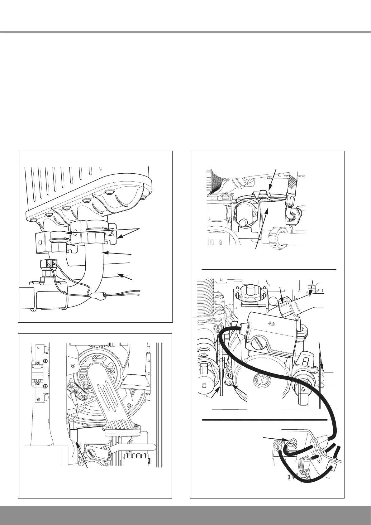
Remove the two connection clips securing the flow and
return pipes to the heat exchanger, see diagram 15.9.
Move the pipes away from the heat exchanger.
Remove the four heat exchanger securing screws and
clamps, see diagram 15.8.
CAUTION: There will be water in the heat exchanger.
Remove the push fit condense pipe from the bottom of the
heat exchanger, see diagram 15.10.
Carefully remove the heat exchanger and disconnect the flue
overheat thermostat, see diagram 13.11.
13444
Diagram 15.10
HEAT EXCHANGER CONDENSATE
CONNECTION (push-fit)

 Loading...


