68
15.33 Access to Control Box Internals
For access, refer to section 15.1.
Carefully pull the control box forwards so that it lies
horizontally in its hinges.
Do not allow the front of the control box to swing down and
be loosely held by its electrical connections.
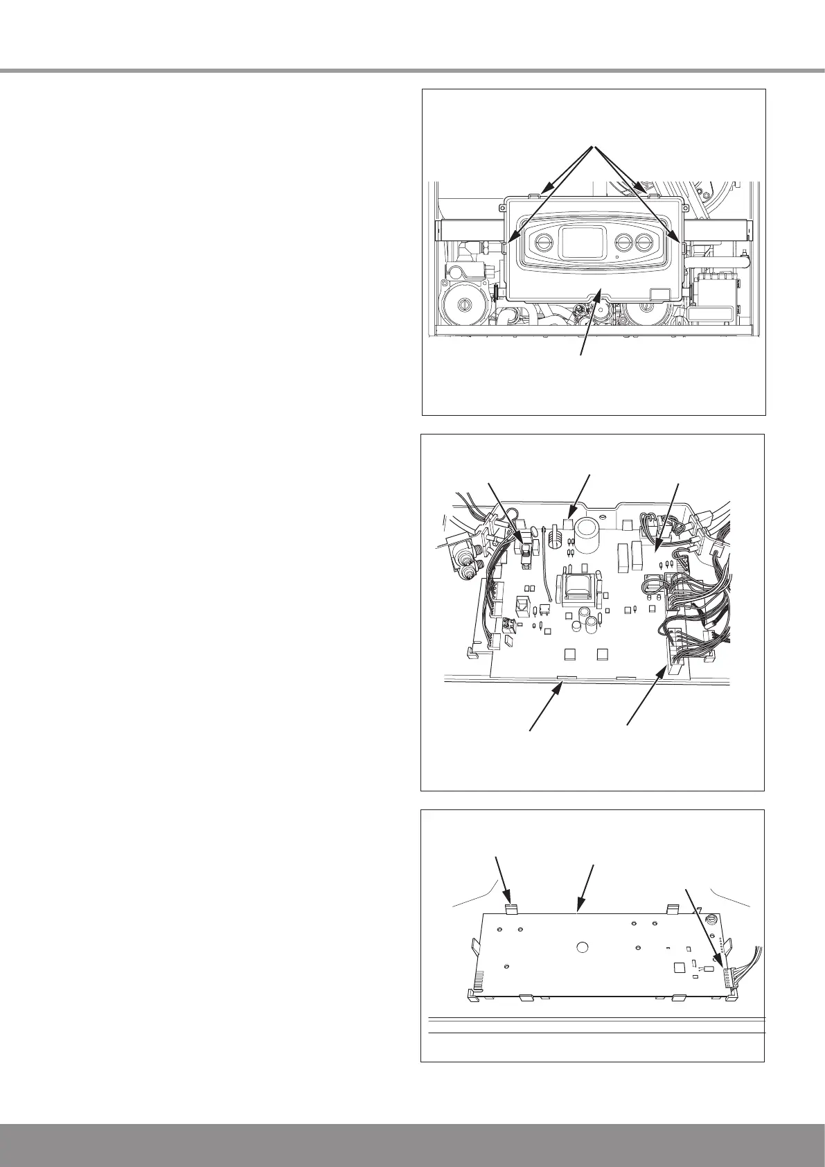
Release the four retaining clips, see diagram 15.27, to
remove the rear cover and gain access to the electrical
connections, main PCB and appliance interface PCB.
15.34 Main PCB
For access, refer to section 15.33.
Remove the electrical connections to the PCB.
Ease back the four PCB retaining clips and withdraw the PCB
from the retaining lugs, see diagram 15.28.
When refitting the control box cover ensure the leads do not
become trapped.
15.35 Fuse, Main PCB - Control Box
For access, refer to section 15.33.
The fuse is located at top left hand side of the main PCB, see
diagram 15.28.
15.36 User Interface
Refer to section 15.33 for access.
Remove the main PCB, refer to section 15.34.
Remove the electrical connection.
Gently ease back the retaining clips, see diagram 15.29.
Withdraw the board.
When replacing the board refer to instructions supplied with
replacement PCB.
15 Replacement of Parts
Diagram 15.29
MAIN PCB
RETAINING
CLIP (4 OFF)
ELECTRICAL
CONNECTION
RETAINING
LUG (2 OFF)
FUSE
Diagram 15.28
13372
Diagram 15.27
13446
USER INTERFACE
BOARD
RETAINING
CLIPS
ELECTRICAL
CONNECTION
13355

 Loading...


