16 Installation and maintenance instructions EASICOM 3 0020238431_03
7 Installation
7.1 Preparing for installation
▶ Make sure that the existing gas meter and the pipelines
are capable of passing the rate of gas supply required.
▶ Consider the maximum heat output given in DHW mode.
▶ Install the following components:
– Draining cocks at the lowest points in the heating
installation (→ current version of "BS 2879")
– A bypass that is at least 1.5 m away from the product
– A stopcock in the gas pipe
– Where applicable, a flow regulator valve to adjust the
flow rate
▶ Install the connection pipes such that they are free from
mechanical stress.
▶ If you use non-diffusion-tight plastic pipes in the heating
installation, ensure that no air gets into the heat gener-
ator circuit.
▶ Only solder connectors if the connectors are not yet
screwed to the service valves.
▶ Only bend connection pipes if they have not yet been
connected to the product.
▶
Flush the heating installation thoroughly before installing
the product.
▶ Check the leak-tightness of the gas valve assembly using
a pressure of ≤ 11 kPa (110 mbar).
7.2 Installing the heating pump
The flow rate must not fall below the value in the diagram.
▶
Only use pumps that have an in-rush current ≤ 10/15 A.
▶ When designing/selecting the pump, note the pressure
loss of the product.
▶ Install the pump in the heating flow.
▶ Install the pump upstream and downstream of the pump
isolation valves.
▶ Set the pump so that the temperature difference between
the flow and return is no more than 20 °C when the max-
imum flow temperature is set.
– The flow rate specified in the technical data is
reached.
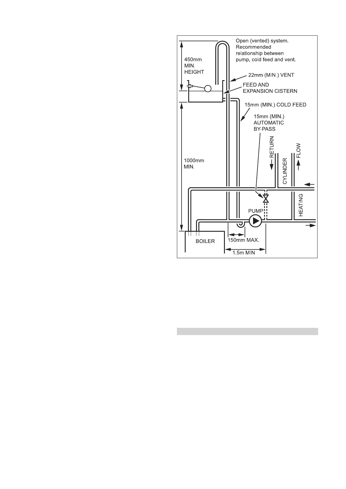
7.3 Heating water supply in the open heating
system
▶ Connect the product to a supply/expansion tank as
shown in the figure.
– The tank must not be more than 27 m (90 ft) above
the product.
– The open vent pipe must be installed with an upward
gradient and must not be blocked.
– Supply pipe diameter: ≥ 15 mm
–
The relative positions of the pump, supply and open
vent pipe must be as shown in the figure.
Condition: Combined supply and open vent pipe
▶ Install the line in accordance with "BS 5449".
– Diameter: ≥ 22 mm