R 22MAR23
PART No.
SHEET
ALL INFORMATION WITHIN ABOVE
BORDER TO BE PRINTED EXACTLY
AS SHOWN ON 8.5 x 11 WHITE 16
POUND
NON-BOND RECYCLABLE
PAPER.
PRINT ON BOTH SIDES,
EXCLUDING TEMPLATES. TO BE
UNITED IN ACCORDANCE
WITH
GMCCA SPECIFICATIONS.
Date Revision Auth DR
Title
Ultium PowerUP Charge Station
User Manual
13DEC22 Fourth Re l SAR
MB
22MAR23
Fifth Re l
SAR
MB
84922762
29NOV22
Third Re l
SAR
AH
10
EN
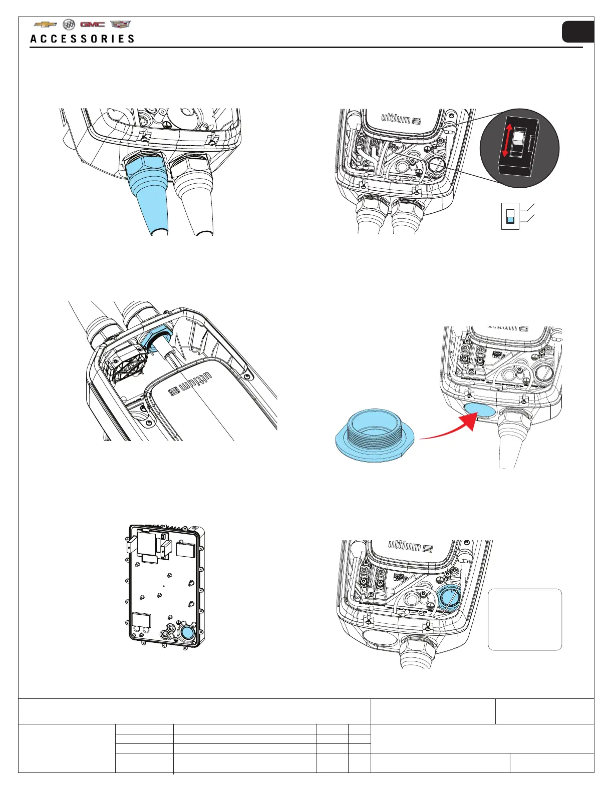
5. Loosen the nut for the cable gland → pull out the
cable.
6. Change the position of the white switch carefully as
illustrated. A small screwdriver is required.
NOTE: failing to do this will produce an error.
NEMA
HARDWIRE
NOTE: Components may have been removed for image clarity.
7. Remove the nut and pull out the cable gland. 8. Insert the blind plug included with the accessory kit
into the opening for the cable gland from the bot-
tom. Secure it with the nut (from Step 1) and tighten
it to 131 ft/lbs(13 Nm).
Refit the cable clamp assembly (from Step 4) to the
remaining cable.
9. Unscrew the blind plug provided in the rear. 10. Make sure a suitable 1” water tight conduit com-
pliant to type 4X and an adapter is used to fit the
1.3 in (33.7 mm) aperture shown → Push the new
(round) cable through the aperture.
NOTE: Components may have been removed for image clarity. NOTE: Components may have been removed for image clarity.
NOTE: Components may have been removed for image clarity.
Make sure the
adapter does not
protrude to the rear
of the unit so that
it will interfere with
wall mounting.