AIR COMPRESSOR AND GOVERNOR 5J-17
Leakage Test
To make a leakage check, apply a soap solution at
the exhaust port in the cut-in and cut-out positions.
•In the cut-in position, check the exhaust port
and the bottom piston grommet.
• In the cut-out position, check the exhaust port
for leakage at the exhaust valve seat or stem
grommet and the upper piston grommet.
After testing, remove the soap.
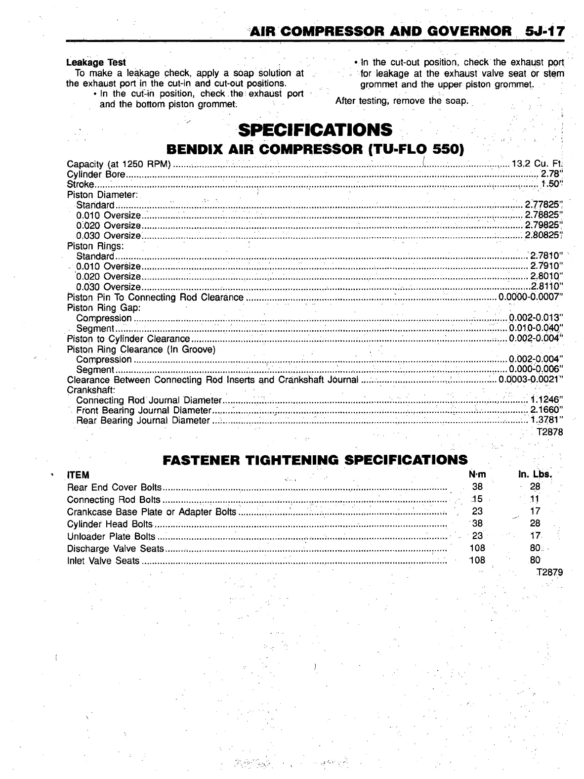
SPECIFICATIONS
BENDIX AIR COMPRESSOR (TU-FLO 550)
Capacity (at 1250 RPM)
......
.
..........
.
................
;....;
...........
.
........
.........
.
.........................
i
.........
....
.
Cylinder Bore
...................................................
.........
........
.
........
..................
.
...................
.
............
.
Stroke
.....
'.
.......
.
......................
.............
.
....
:
.......
.
......
.
..........
.
....................................
.
...................
........
Piston Diameter: '
Standard..............
.......
............
.................................................................
.....
.
....................
......
.
.......
0.010 Oversize..'...........
................
......................
.........
................................ .......................
....
.......
0.020 Oversize
..................................
........
............................................
.
................
....................
0,030 Oversize.
.....................
.
.......
......
.....
..........
...............................................
.
............
......
.
........
Piston Rings:
Standard................................................
.
.........
.
..................................
.......................
.
..........
.
..........
0.010 Oversize
..............
....................
.
...........................
.....................
........
.
.......
.
.................
.
........
0.020 Oversize
...............
...;
.......
,
........
.
...............................
.
.................
.
.........................................
0.030 Oversize...............................
.
...
......................
.
.......
.
.......
...........................
...................
.
........
Piston Pin To Connecting Rod Clearance
.
...............................................................................
........
Piston Ring Gap:
Compression
................
.
..................
.
.......................
.
............................ ...........
.
..................
.
..........
Seg ment
.
...........
........................................
.
.....
.
........................
.
.............. ......
.............................
.....
Piston to Cylinder Clearance
.......................
.
....................
.
....................
.
.................
.............
......
Piston Ring Clearance (In Groove)
Compression
......................................
.
.
.
.
.....
.
............
.
........................
..
.
.....
.........
.
...........................
Segment................................................
............
..................
.
.........
.
.............
.
.....................
.
Clearance Between Connecting Rod Inserts and Crankshaft Journal
.
............... ...........
Crankshaft:
Connecting Rod Journal Diameter............
.
...................................
..........
.
.
........
.
Front Bearing Journal Diameter...
....
......
.
.........
;
.................
........................
.
........
.........
.
Rear Bearing Journal Diameter...:
......
.
..............
.
........
.
................................... .
.................
.
.....
13.2 Cu. Ft;
.......
...2.78”
........... 1.50”
. 2.77825”
„ 2.78825”
. 2.79825"
. 2.80825”
.
............
2.7810”
............
2.7910”
......
2.8010”
....:
.......
2.8116”
0.0000^0.0007”
...0.002-0.013”
....0.010-0.040”
.... 0.002-0.004”
...0.002-0.004”
....0.000-0.006”
0.0003-0.0021”
.....
.
1.1246”
..........
.
2.1660”
.
............1.3781”
: ■ T2878
FASTENER TIGHTENING SPECIFICATIONS
ITEM v N m In. Lbs.
Rear End Cover Bolts
.................
38 28
Connecting Rod Bolts
..............
15 11
Crankcase Base Plate or Adapter Bolts
......
....................
23 17
Cylinder Head Bolts
........
.
..................
38 28
Unloader Plate Bolts
.
.....................
23 17-
Discharge Valve Seats
.......
.
..........................
,.
.................
.
.......
...........................
.
.............. ......
108 80,
Inlet Valve Seats
......................................
.
...........
......................
,
............
.........
.
.....................
:... 108 80
T2879
 Loading...