6A2-6 V8 ENGINES, GASOLINE
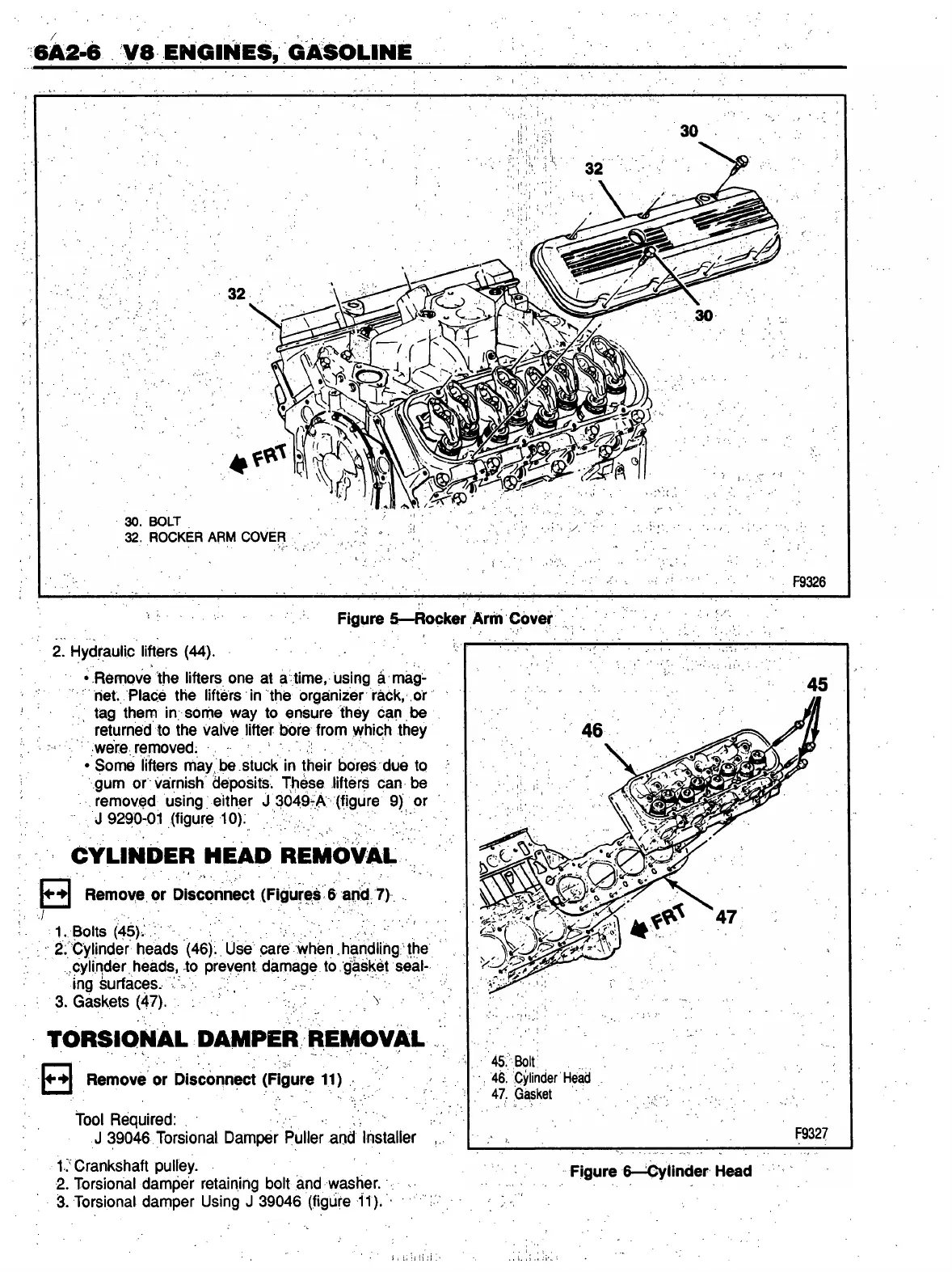
F i g u r e 5 — R o c k e r A r m C o v e r
2. Hydraulic lifters (44).
• Remove the lifters one at a time, using a mag
net. Place the lifters in the organizer rack, or
tag them in some way to ensure they can be
returned to the valve lifter bore from which they
were removed.
• Some lifters may be stuck in their bores due to
gum or varnish deposits. These lifters can be
removed using either J 3049-A (figure 9) or
J 9290-01 (figure 10). S ;
CYLINDER HEAD REMOVAL
R e m o v e o r D i s c o n n e c t ( F i g u r e s 6 a n d 7 )
1..Bolts (45). , / v; ' .
2. Cylinder heads (46). Use care when . handling the
cylinder heads, to prevent damage to gasket seal
ing surfaces.
3. Gaskets (47). ; v .
TORSIONAL DAMPER REMOVAL
R e m o v e o r D i s c o n n e c t ( F i g u r e 1 1 )
tool Required:
J 39046 Torsional Damper Puller and Installer
1. Crankshaft pulley.
2. Torsional damper retaining bolt and washer.
3. Torsional damper Using J 39046 (figure 11).
 Loading...