Go Power! DC Install Kit
Owner’s Manual
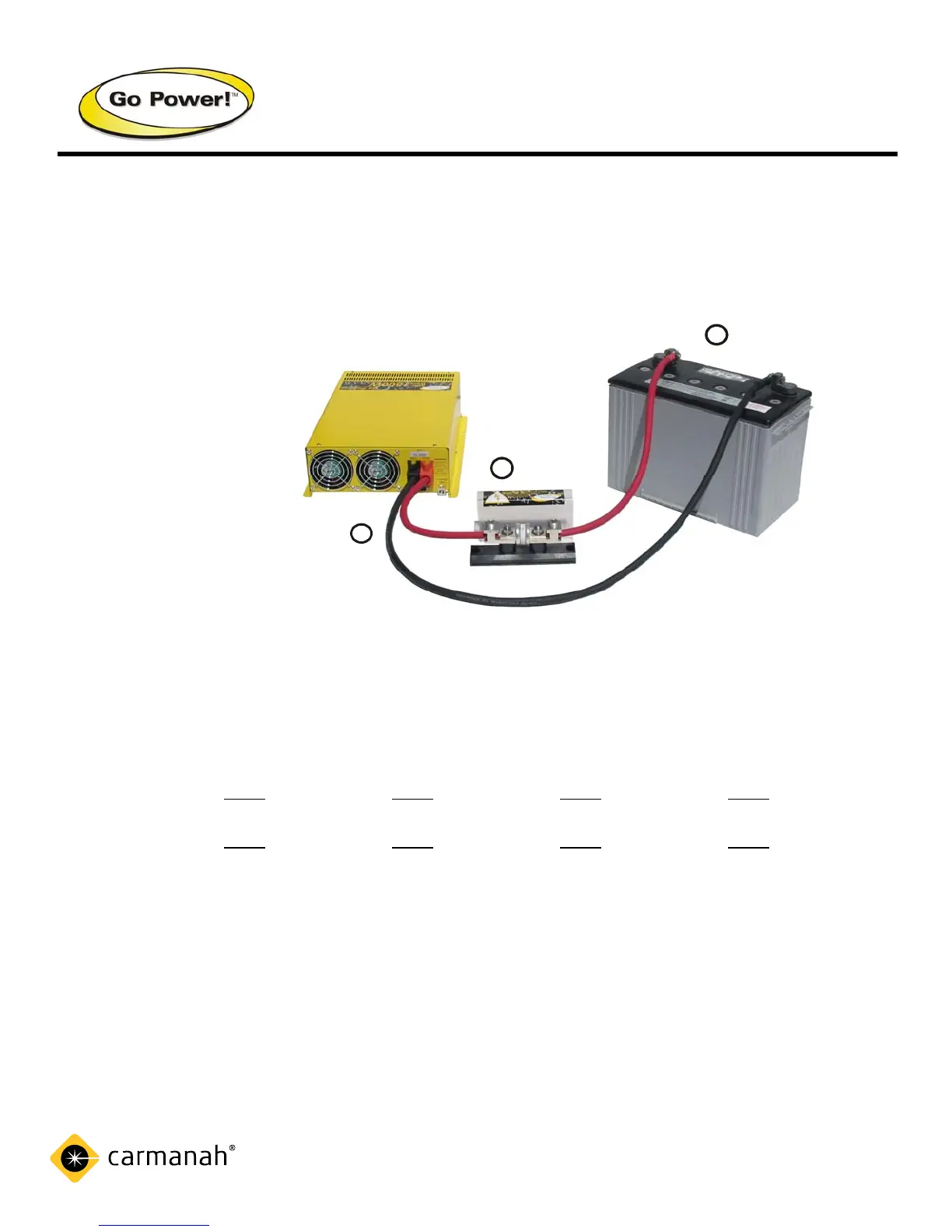
3. Tighten the lugs to 10 ft. lbs.
4. Observe the polarity of the cables (red = positive) (black = negative) and connect
accordingly to the inverter.
3.1 Installation Diagram
4. Specifications
Kit 2 Kit 3 Kit 4 Kit 5
Fuse Size 110 amp fuse 200 amp fuse 300 amp fuse 400 amp fuse
Cable Gauge IC #4 – 10 ft. IC #2 – 10 ft. IC 2/0 – 10 ft. IC 4/0 – 10 ft.
Inverter 12 volt
12 volt 12 volt 12 volt
600-1000 watt 1100-1800 watt 2000-2500 watt 2600-3000 watt
24 volt
24 volt 24 volt 24 volt
600-1800 watt 2000-3000 watt 3100-4000 watt 4100-6000 watt
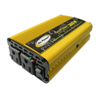
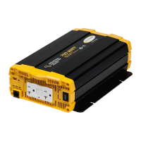
Go Power! GP-1000, GP-SW600, GP1750, GP-SW2000-12 GP-SW3000-12
Quick Check GP-SW1000, GP-SW1500-12 GP2500
GP-SW1500-24 GP-SW2000-24
GP-SW3000-24
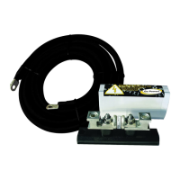
Included Items GP-Fuse Block 110, GP-Fuse Block 200, GP-Fuse Block 300 GP-Fuse Block 400
IC-4-10 cable, 11.5” IC-2-10 cable, 11.5” IC-2/0-10 cable, 11.5” IC-4/0-10 cable, 11.5”
40 lb. Black, Tie wraps 40 lb. Black Tie wraps 40 lb. Black Tie wraps 40 lb. Black Tie wraps
(6), 3/8” cable clamps (6), 1/2” cable clamp (6), 3/4” cable clamps (6), 3/4” cable clamps
(6), #6 x 3/4” pan (6), #6 x 3/4” pan (6), #6 x 3/4” pan #6 x 3/4” pan
head screws (6) head screws (6) head screws (6) head screws (6)
Technical Support: info@gpelectric.com
Toll Free (US & Canada): 1-800-667-6527
Toll Free Fax: 1-866-607-6527
GP Inverter
Battery
Fuse
Block
3
2
1
-
+