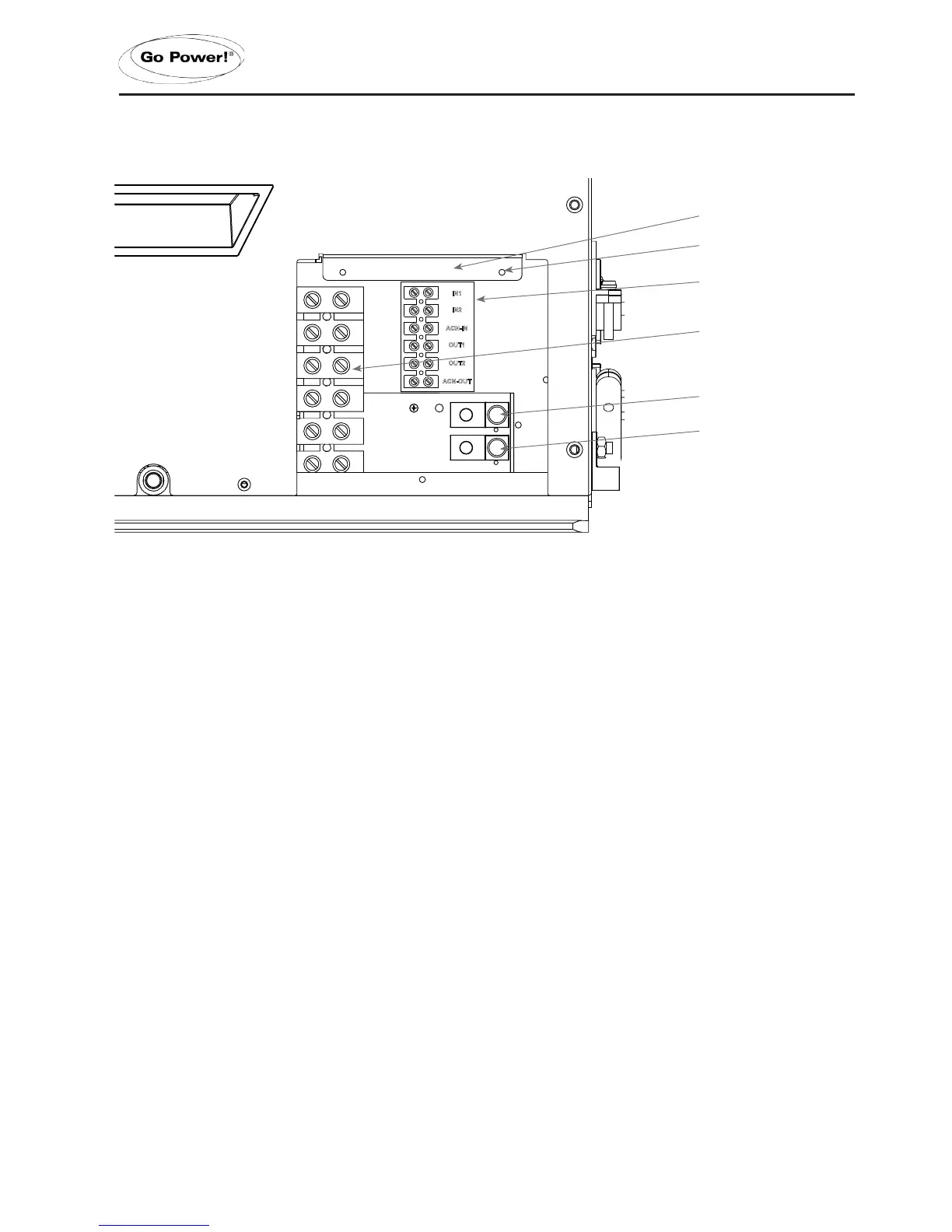
Terminal label
Phillips screw boss x3
AC ground IN
(from main panel)
AC ground OUT
(to sub panel)
AC cover plate removed
AC terminal block
3.6.4 AC TERMINAL BLOCK CONNECTIONS
The IC Series has a six-pole AC terminal block and two AC ground terminals to connect the Inverter/Charger’s AC input and
output wiring.
The terminal block and ground terminals can be accessed by removing the three Phillips screws holding the AC cover plate.
Each connection on the AC terminal block is rated to accept one #14 to #6 AWG CU stranded wire, or two #12 AWG CU
strandedwires.Useaatheadscrewdrivertoreleaseandtightenthesetscrews.
TheACgroundterminalscanaccepttwo#14to#6AWGCUstrandedwire.Useaatheadscrewdrivertoreleaseandtighten
the set screws.
The IC Series’ ACN-IN and ACN-OUT terminals are electrically isolated from each other when in “inverting mode”, which
helps to prevent ground-loops. If the installation requires the AC Input and AC Output neutrals to be connected together, the
Inverter/Charger’s neutral-to-ground connection must be disconnected (See section 3.6.11).
INSTALLATION
 Loading...