page 4 | gpelectric.com
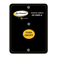
4. INTRODUCTION
3
4
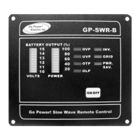
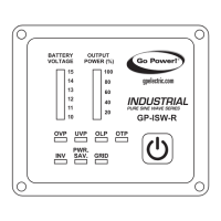
BATTERY VOLTAGE INDICATOR
Battery voltage indicator will move up and down as the battery voltage changes.
Ideally, the voltage should remain in the green area of the bar chart.
If the voltage goes into the red area at the top and bottom of the bar chart, the
inverter may shut down.
OTHER INDICATORS
• OVP (Over voltage protection):
Indicates that the inverter will shut down because its input voltage is above the
voltage limit.
• UVP (Under voltage protection):
Indicates that inverter will shut down because its input voltage is below the
voltage minimum.
• OLP (Overload protection indicator):
Indicates the inverter will shut down due to a short circuit or overload
protection.
• OTP (Over temperature protection indicator):
Indicates the inverter will shut down due to over temperature protection. Once
the inverter cools down, the indicator will turn off automatically.
• INV indicator:
Indicates the inverter is ready.
• PWR. SAV. indicator:
Power saving functions are described below:
LED Meaning Inverter Output
Solid Ready ON
Flashing Active OFF
Off Inactive
• GRID indicator:
Indicates the AC Grid is connected to the inverter (only functional when
connecting inverter series with Transfer Relay).
 Loading...