gpelectric.com | page 3
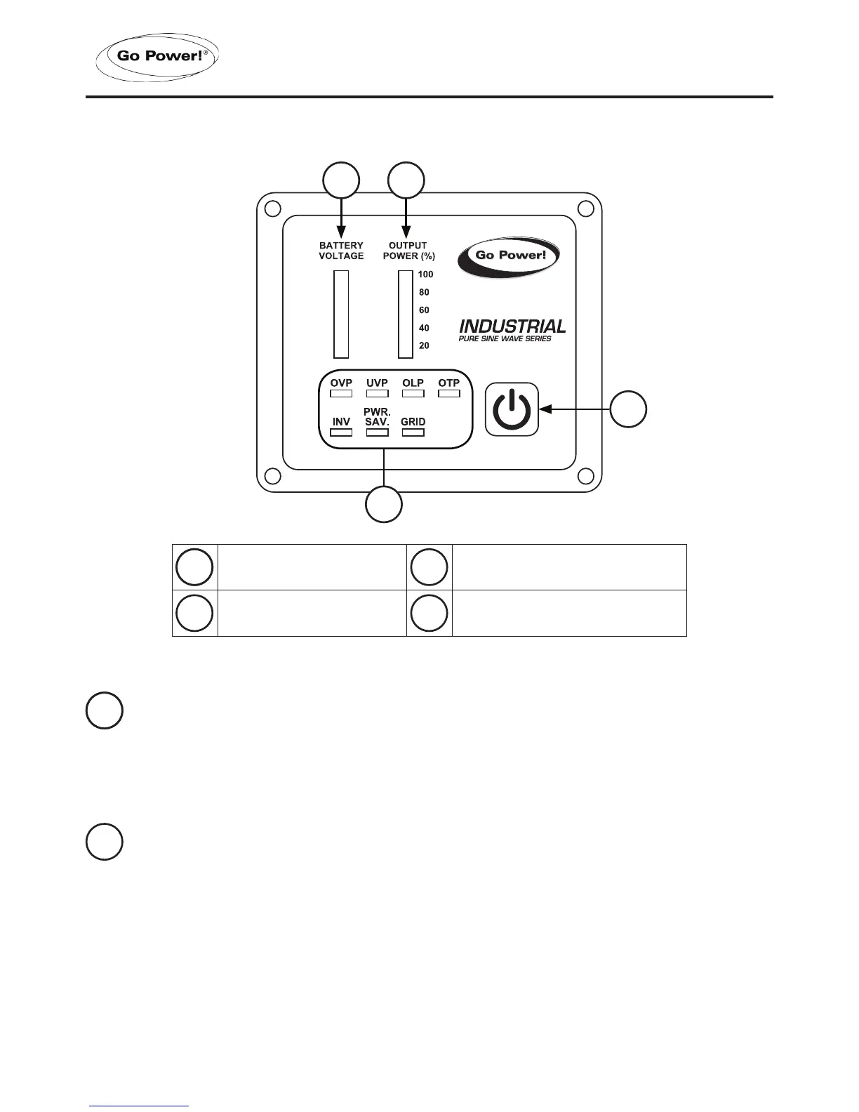
4.1 FRONT PANEL INTRODUCTION
gpelectric.com
GP-ISW-R-12
15
14
13
12
11
10
®
1
3 2
4
11 POWER ON/OFF BUTTON
Power ON/OFF button turns the inverter on or off.
2 OUTPUT POWER INDICATOR
Output power indicator shows the power draw from the inverter by the load. Ideally,
the output power indicator should remain in the green & orange area of the bar
chart.
If the output power indicator is up to the red area, the OLP LED will ash and the
inverter will shut down.
Power ON/OFF button Battery voltage indicator
Output power indicator Other indicators
11 3
2 4
Note: the 24 volt inverter remote’s Battery voltage
indicator reads “20, 22, 24, 26, 28, 30.”
4. INTRODUCTION
 Loading...