Do you have a question about the Go Power GP-RVC-MPPT-30 and is the answer not in the manual?
General safety guidelines including reading the manual, voltage warnings, and terminal block checks.
Specific safety instructions for connecting solar arrays and handling controller voltage limits.
Safety advice for battery connection, type selection, and charging precautions.
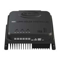
Explains the 30A RV-C MPPT solar controller's role in smart RV systems and its core functions.
Lists advanced features like MPPT, multi-peak tracking, lithium battery reset, and temperature compensation.
The initial stage where the controller uses MPPT to charge the battery at maximum solar energy.
Constant voltage charging stage where current gradually decreases as the battery approaches full charge.
Low current stage to maintain battery voltage, switching back to bulk if voltage drops significantly.
Identifies the controller LEDs and their meanings for PV and battery status indication.
Details the status of the PV indicator LED for different operational states like night time, MPPT, and float charging.
Explains the battery indicator LED patterns for states such as no battery, over-voltage, and normal operation.
Lists essential tools and materials required for installing the solar controller.
General guidance on selecting an installation location and preparing for wiring.
Criteria for selecting a suitable indoor location, considering ventilation, temperature, and proximity to the battery.
Steps for marking mounting points, drilling holes, and securely attaching the controller to a surface.
Instructions for connecting PV and battery wires, emphasizing wire size, fuses, and safety precautions.
Explains how to identify the RV-C instance number using the controller's LEDs.
Provides a step-by-step guide on configuring the RV-C network instance using the SET button.
| Battery Voltage Range | 8V – 32V |
|---|---|
| Battery Type | Lead Acid (AGM, GEL, Flooded), LiFePO4 |
| Max Charge Current | 30A |
| Conversion Efficiency | ≤98% |
| MPPT Tracking Efficiency | >99% |
| No-Load Loss | <10mA |
| Max Panel Input Voltage | 100Voc |
| Max PV Power Input | 600W@12V / 1200W@24V |
| Grounding | Negative |
| Protection | Solar/battery reverse polarity Solar/battery over voltage Solar/battery short circuit Over temperature |
| Operating Temperature | -35 to 45°C |
| Storage Temperature | -35 to 75°C |
| Humidity | 95% N.C. |
| Water Ingress Protection | IP32 |
| Altitude | < 3000m |
| Max Wire Gauge | 8 AWG |
| Dimensions (H x W x D) | 3.15” x 7.78” x 5.5” |
|---|---|
| Weight | 3.14lbs (1.42kg) |