Repair Manual
Corporate Division
Off-Road Driveline Technology
and Axle Systems
5871 214 102 5/11
1
3
2
Tighten Torx screws (arrow 2).
Mount stub shaft to the portal drive. Grease the O-ring and fit it
to the axle housing half (arrow 3). Bring portal drive and stub
shaft into contact position with the axle housing half (arrow 3)
and fix it by means of Torx screws (arrow 1).
Tightening torque (Torx screws) M
A
= 185 Nm
(S) Eyebolt AA00 609 603
Figure 36
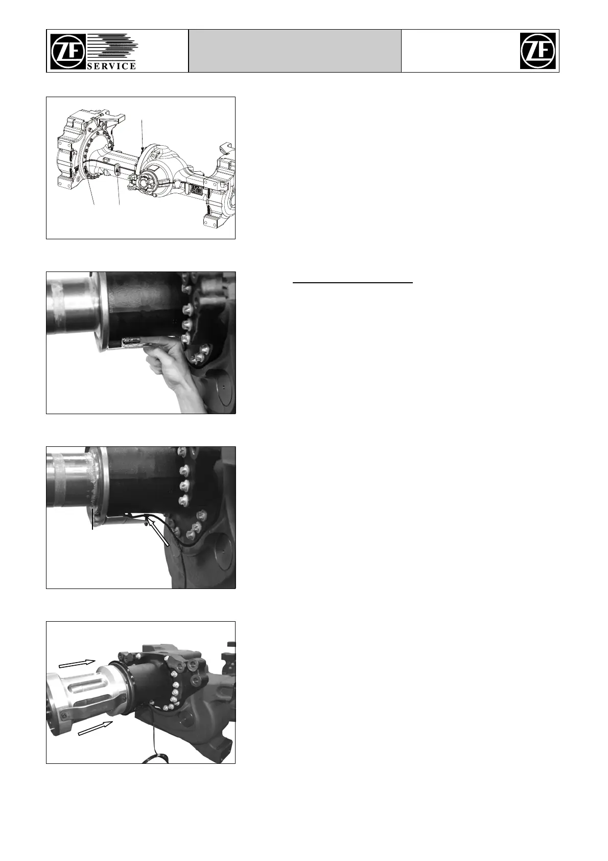
5.4 Revolution counter
Mount bushing to the hub carrier until contact position.
Figure 37
Wet outside surface of revolution counter with silicone grease.
Then mount revolution counter to the bushing until it protrudes
approx. 1 … 3 mm on the contact face of the compact bearing
(see black line).
Then install clamp (see arrow) and mount cable.
Figure 38
Mount the pressing device (S) to the hub carrier with the recess
facing downwards (6 o’clock position).
Position the revolution counter by pressing against it manually
until contact with utmost care.
(S) Pressing device AA00 387 830
Do not rotate the pressing device (S). Otherwise the
revolution counter might be damaged.
Figure 39