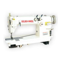
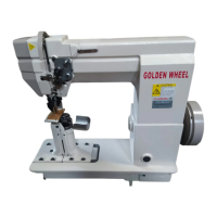
This document is an instruction manual for the Golden Wheel Industrial Sewing Machine models CS-5940/5941 and CS-5942/5942T. It covers setup, care, maintenance, and adjustment procedures for these machines.
Function Description:
The Golden Wheel Industrial Sewing Machine is designed for various sewing operations, with specific models potentially offering different functionalities such as thread trimming and tension release. The manual details the mechanical adjustments required for precise sewing, including needle positioning, feed dog movements, and looper thread regulation. The CS-5942/5942T models feature pneumatic presser foot lifting and thread tension release mechanisms, indicating advanced automation for improved efficiency and ease of use in industrial settings.
Important Technical Specifications:
Oil:
- Machine Oil Level (General): The oil level must be between the markings in the inspection glass. Refill through hole 1 if necessary.
- Machine Oil Viscosity (General): Use oil with a mean viscosity of 22.0mm²/s at 40°C and a density of 0.865 g/cm³ at 15°C.
- Lubricating Top Feed Joints: Use oil with a medium viscosity of 10.0 mm²/s at 40°C and a density of 0.847 g/cm³ at 15°C.
Air Pressure (CS-5942/5942T specific):
- Operating Pressure: The air pressure on gauge 1 must show a pressure of 6 bar.
- Pneumatic Pressure of Demand: 6mpA.
Needle Height (at t.d.c., adjustment hole 1):
- CS-5940: Distance X between needle plate and needle tip should be 11 mm.
- CS-5941: Distance X between needle plate and needle tip should be 14 mm.
Feed Dog Position (at t.d.c., adjustment hole 1, stitch length set at longest):
- Main Feed Dog (General): Should be 1.4mm parallel above the needle plate.
- Differential Feed Dog (General): Should be 0.9mm parallel above the needle plate.
- Feed Dog Positioning (General): Both feed dogs should be in the centre of the needle plate cutout.
- Feed Dog Spacing (General): The two feed dogs should be spaced 4 mm apart.
- Main Feed Dog (CS-5941): Should be 1.7mm parallel above the needle plate.
- Differential Feed Dog (CS-5941): Should be 2.0mm parallel above the needle plate.
Top Feed Dog Stroke (stitch length set at "4", adjustment gauge 12 fitted, at t.d.c.):
- Distance from Needle Plate: The top feed dog 2 should be 3.2mm from the needle plate.
Looper Thread Regulator and Take-Up:
- Distance (Regulator 1 to Needle Plate Guide): 29mm between the front edge of looper thread regulator 1 and the rear edge needle plate guide.
- Distance (Take-Up Device 3 to Regulator 1): Approximately 8mm between the front edges of the thread take-up device 3 and the thread regulator 1.
Looper Thread Puller (needle bar in top dead center, pin in hole 1):
- Position: Both eyes of looper thread puller 1 must be at the front edge of the thread take-up device 4. The prongs of thread puller 1 should be in the middle of thread regulator 3.
Usage Features:
Setup:
- Inserting the Needle: The needle bar is set at its highest point, screw 1 is loosened, needle 2 is pushed fully into the needle bar with the long needle groove facing front, and screw 1 is tightened.
- Threading the Needle Thread: Thread the needle as shown in the figure and regulate tension by turning knurled nut 1.
- Threading the Looper Thread: Open the looper cover, swing out thread guide plate 1, thread the looper thread under guide plate 2, and regulate tension by turning knurled nut 4.
Adjustment:
- Control and Adjustment Aids: An adjustment pin (ø 5mm) can be inserted into marked holes (1, 2, 3, 4) to precisely fix needle bar positions.
- Hole 1: Top dead centre of needle bar (t.d.c.)
- Hole 2: Bottom position of top feed dog
- Hole 3: Bottom dead centre of needle bar (b.d.c.)
- Hole 4: Neutral position of main feed dog and differential feed dog
- Needle to Needle Hole: Needle 5 should be in the center of the needle hole, with a distance of approximately 0.8mm between needle 5 and the front edge of the needle hole. Adjustment involves loosening screws 1 and 2, adjusting needle bar frame 3, and then tightening.
- Preliminary Adjustment of Needle Height: Bring the needle bar to t.d.c. and adjust its height (using screws 2) to meet the specified distance X (11mm for CS-5940, 14mm for CS-5941).
- Neutral Position of Main Feed Dog: Set stitch length to "0". Loosen screw 1 and nut 2. Loosen screw 4. Adjust crank 5 while turning the balance wheel so that crank 6 does not move. Tighten screw 4.
- Neutral Position of Differential Feed Dog: Set stitch length to "0" and fit adjustment gauge 1. Loosen screw 2. Adjust crank 3 while turning the balance wheel so that crank 4 does not move. Tighten screw 2.
- Feeding Motion of Main and Differential Feed Dog: Set stitch length to "4", position needle bar at adjustment hole 4, and fit adjustment gauge 8. Loosen screws 1 and 2. Move roller 5 up and down while turning eccentrics 6 and 7 until cranks 3 and 4 do not move. Tighten screws 1 and 2.
- Lifting Motion of Main and Differential Feed Dog: Bring needle bar to t.d.c. Loosen screws 1 and 2. Turn eccentrics 3 and 4 so their cutouts point straight downward. Tighten screws 1 and 2.
- Lifting Motion of Main Feed Dog: Bring needle bar to t.d.c. Loosen screws 1. Turn eccentric 2 so its cutout points straight downward. Tighten screws 1.
- Lifting Motion of Differential Feed Dog: Position needle bar 5.5 mm before t.d.c. Loosen screws 1. Turn eccentric 2 so its cutout points straight downward. Tighten screws 1.
- Position of Main and Differential Feed Dog: Bring needle bar to t.d.c. and set stitch length to longest. Loosen screws 1, 2, 3, and 4. Adjust feed dog carriers 5 and 6, then eccentric bushes 7 and 8, to meet the specified heights, centering, and spacing. Tighten all screws.
- Position of Main and Differential Feed Dog on CS-5941: Set stitch length to longest and bring feed dogs to their highest position. Adjust carrier 1 (using crank 2 and 3, loosening screws 4 and 5, and eccentric clamp bush 6) and differential feed dog carrier 7 (using crank 8 and 9, loosening screws 10 and 11, and eccentric clamp bush 12) to meet the specified heights, centering, and spacing.
- Neutral Position of Top Feed Dog: Set stitch length to "0" and fit adjustment gauge 4. Turn crank 1 (screw 2) while continuously turning the balance wheel so that lever 3 does not move.
- Feeding Motion of Top Feed Dog: Set stitch length to "4", position needle bar at adjustment hole 4. Loosen screws 1. While continuously moving lever 2 up and down, adjust eccentric 3 so its slot points towards the operator and lever 4 does not move. Tighten screws 1.
- Top Feed Stroke: Allow presser foot 1 to touch the needle plate. Set stitch length to "4". Bring top feed dog 2 to t.d.c. Adjust eccentric pin 3 (screw 4) so its eccentric part points towards the needle. Move pin 5 (nut 6) to the bottom of lever 7's elongated hole. Adjust lever 8 (screw 9) to pre-set the distance of top feed dog 2 from the needle plate. Adjust eccentric pin 10 (screw 11) to meet the 3.2mm requirement.
- Lifting Motion of Top Feed Dog: Set stitch length to "4" and fit adjustment gauge 3. Adjust eccentric 1 (screws 2) so the top feed dog rests on the ascending bottom feed dog when it reaches the top edge of the needle plate.
- Looper Avoiding Motion: Bring needle bar to t.d.c. Loosen screw 1. Adjust eccentric 2 so its cutout is positioned vertically below the center of the axis. Tighten screws 1.
- Looper Motion: Insert a new needle. Turn the balance wheel until the looper point from the right is on the left side of the needle. Measure the vertical distance between the bottom of the needle bar frame and the top of the needle clamp. Turn the balance wheel against the sewing direction until the same vertical distance is measured. Adjust gear 1 (screws 2) if necessary.
- Final Adjustment of Needle Height: Turn the balance wheel until the looper point from the right reaches the left side of the needle. Without turning the balance wheel, adjust the height of needle bar 1 (screw 2) so the top edge of the needle eye is 1.0~1.2mm below the bottom edge of the looper.
- Height of Rear Needle Guard: Bring the needle bar to b.d.c. Adjust needle guard 1 (screw 2) so its vertical surface covers about 2/3 of the needle eye.
- Position of Front Needle Guard: Bring looper 1 to its left point of reversal. Loosen screws 2. Adjust needle guard bracket 3 so front needle guard 4 is not in contact with looper 1. Slightly tighten screws 2. Turn the balance wheel until looper 1 from the right is in the center of the needle. Adjust needle guard bracket 3 to meet the 0.3~0.5mm side clearance requirement. Align front needle guard 4 (screws 5) to be parallel to the looper blade and have its top edge at the same height as looper 1's point.
- Looper Thread Regulator and Looper Thread Take-Up: Adjust thread regulator 1 (screws 2) for a 29mm distance. Adjust thread take-up device 3 (screw 4) for an 8mm distance. Note that these settings may need modification based on material and thread.
- Looper Thread Puller: Bring needle bar to top dead center. Turn thread puller 1 (screw 2) so both eyes are at the front edge of thread take-up device 4 and its prongs are in the middle of thread regulator 3. Note that these settings may need modification based on material and thread.
- Pneumatic Presser Foot Lifting Mechanism (CS-5942/5942T): Adjust the pneumatic presser foot lifting cylinder using the air volume regulating valve. The knee presser foot lifting switch activates this function.
- Thread Tension Release Mechanism (CS-5942/5942T): Figure 1 shows the wiper surface thread air cylinder. Presser figure 2 can release thread. Upper feed adjustment rod (3) and lower adjustment rod (4) allow adjustment of upper and lower feed amounts by stirring their respective movements.
- Installation Position of Thread Trimming Positioner (CS-5942/5942T): Adjust the outer positioner to align the red point on the handwheel with the red point on the machine head. The outer positioner needs a position plate, with A for upper stop and B for lower stop.
Maintenance Features:
- Machine Oil Level: Check before each use. Refill oil through hole 1 if required, ensuring the level is between the markings.
- Lubricating Top Feed Joints: Lubricate the marked points with a drop of oil once a week or after the machine has been idle for longer periods.
- Checking and Adjusting Air Pressure: Before operating, always check the air pressure on gauge 1. It must show 6 bar. Adjust by pulling knob 2 upwards, turning it to 6 bar, then pressing it down.