2
SAFETY PRECAUTIONS
- ."HZ" input for calls from apartment front door Up to 8 monitors/ apartments with push
button "HZ" activated at the same time (with system and monitors in standby).
Important:
- .Installer menu
- .User menu
- eds.Notification l
- 50mA/12V ).Output auxiliary call repeater (max. dc
- .Image and communication settings menu
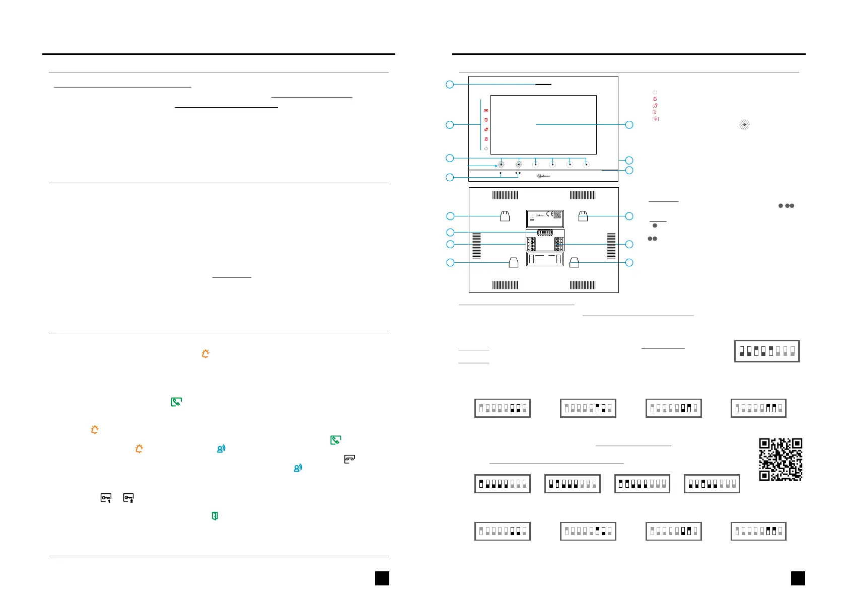
- .Configuration switches to assign the address and to define whether the monitor is master or slave
- Hidden push buttons for Door release 1 and 2.
-
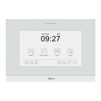
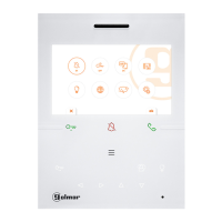
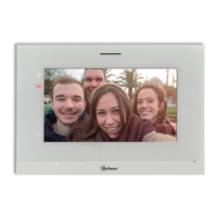
Hands-free monitor.
- olo r .7" TFT c u screen
- for access and selection of menu function.Hidden push button
- Monitor .with simple installation (non-polarised 2 wires bus)
.
- before installing or making modifications to the device.Always disconnect the power supply
- The fitting and handling of these devices must be carried out by .authorised personnel
.
-
Always follow the instructions contained in this manual.
- Install the monitor in a dry protected location free from the risk of dripping or splashing water.
- The wiring must run at least 40 cm. away from any other wiring.
- Do not place in humid, dusty or smoky locations, or near sources of heat.
- Before connecting the device to the mains, check the connections between the door panel, power
supply, distributors and monitors.
- Do not overtighten the screws on the connector.
CHARACTERISTICS
SYSTEM OPERATION
*
( )
3
DESCRIP MONITORTION
Monitor address (code) setup:
*
( )
*
( )
*
( )
INSTALA MONITORTION OF THE
*
( )
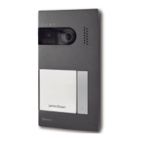
Building / Villa (Nexa Door Panel)
Master Slave 1 Slave 2 Slave 3
Dip8: This activates the end-of-line resistance in the ON position. Activate it in monitors where the bus cable
ends. Deactivate it only in intermediate monitors.
Dip6-Dip7: These define whether the monitor is master or slave. Each apartment must have one master monitor, and only
one. In the case of apartments with more than one monitor, the monitor with Wi-Fi transmitter should always be the master.
Dip1 Dip5:- Sets the monitor address (addresses to 3 ).1 2
The switches set to OFF have a zero value. The values of the switches set to ON are shown in the table below. The
monitor code is the sum of the values of the switches set to ON.
*
( )
ENEN
ART 7/G2+ MONITORART 7/G2+ MONITOR
- or , hidden push button below of
displayed on the screen
To open door of the door panel press the corresponding icon
during the call or communication processes: one press will activate the lock
release for seconds and LED will also turn on for seconds. If vocal synthesis is
enabled, a 'Door open' message will be indicated on the door panel.
3 3the door panel
is
- Detailed operation of the monitorand configuration , see "TART /G2+" user manual7 monitor .
- Upon receiving the call, the image will appear on the screen of the master monitor (and slave 1, if it exists)
without the visitor knowing and icon displayed on the screen will blink green. To view the image from
slave monitors 2 or 3, press the one of the hidden buttons (located above the raised dots for the visually
impaired) of the monitor to display the door
panel
the image. If the call is not answered within 45 seconds,
LED will turn off and the system will become free.
- To establish communication, press off-the-hook icon on the
screen. Door panel LED will .
the hidden push button below shown
will turn off and the led turn on
- the hidden push button below shown on
the is pressed door panel
Connection will last for 90 seconds or until on-the-hook icon
on the screen . When communication ends, LED will turn off and the system
will become free. If vocal synthesis is enabled, a 'Communication is finished' message will indicate that
the call is over.
-
To make a call, the visitor must press the button of the apartment; an audible sound indicates that the
call is being made and LED will turn on. If vocal synthesis is enabled, a 'Call is in
progress' message appears indicating that a call is being made. At this moment, the apartment's
monitors receive the call. If another apartment is called by mistake, press the button for the correct
apartment and the first call will be cancelled.
the door panel
1
2
*
1 2 3
ON
4 5 6 7 8 1 2 3
ON
4 5 6 7 8 1 2 3
ON
4 5 6 7 8 1 2 3
ON
4 5 6 7 8
1 2 3
ON
Example: 0+ 0+4+0+16 = 20
Switch number:
Value when ON
1 2 3 4 5
:1 2 4 8 16
Table of values
4 5 6 7 8
Important: Apartment 1 (Dip1 to ON & Dip2-Dip5 to OFF).
Important: Apartment 32 (Dip1 - Dip5 to OFF).
Villa (Soul Door Panel)
Dip1 to Dip5: These assign the address of the corresponding monitor to its call button on the door
panel. Switches 4-5 must remain in the OFF position.
1 2 3
ON
4 5 6 7 8 1 2 3
ON
4 5 6 7 8 1 2 3
ON
4 5 6 7 8 1 2 3
ON
4 5 6 7 8
Apartment 1 Apartment 2 Apartment 3 Apartment 4
*
Dip8: This activates the end-of-line resistance in the ON position. Activate it in monitors where the bus cable ends.
Deactivate it only in intermediate monitors.
manual
Kit Soul / Art 7
Dip6-Dip7: These define whether the monitor is master or slave. Each apartment must have one master monitor,
and only one.
Master Slave 1 Slave 2 Slave 3
1 2 3
ON
4 5 6 7 8 1 2 3
ON
4 5 6 7 8 1 2 3
ON
4 5 6 7 8 1 2 3
ON
4 5 6 7 8
*
( )
For more information, see user manual“TART 7/G2+ (cód. 50122464)”.
https://doc.golmar.es/search/manual/50122464
( )
For more information, see user manual“TART 7/G2+ (cód. 50122464)”.
https://doc.golmar.es/search/manual/50122464
G
A
E
B
C
D
F
SA
GND
HZ
HZ
BUS
IN
OFF = 0 | ON = 1
DIP 1 to 5
DIP 8
Monitor address
End of line resistor
DIP 6,7
00 - Master
10 - Slave 1
01 - Slave 2
11 - Slave 3
BUS
OUT
H
I
J
H
H
H
J
SA
GND
HZ
HZ
BUS
IN
ON
1 2 3 4 5 6 7
8
*
12210701 V0Product Version: 3
MONITOR 7” ART 7/G2+
GOLMAR S.A.
C/ Silici, 13
08940 - SPAIN
WARNING
TO PREVENTFIRE OR ELECTRIC
SHOCK, DO NOT EXPOSETHIS
DEVICE TO RAIN OR MOISTURE
TO PREVENTELECTRIC SHOCK,
CAUTION
DO NOT REMOVE COVER. NO
USER SERVICEABLE PARTS
INSIDE. REFER SERVICINGTO
QUALIFIED SERVICE PERSONNEL.
MADE IN CHINA
BUS
OUT
Hidden button
pressing area
BUS
OUT
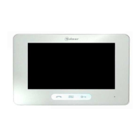
E. TFT colour screen.7"
G. Micro SD card slot (not included).
A. Speaker.
In call:
H. Wall mounting connector fixing (x4).
I. Configuration switches.
In standby:
T p : MicroSD Clas 10 4Gb 128Gb.y e s from to
Power on indicator.
New image/video.
C. Hidden push button indicator Leds :
Auxiliary relay activated.
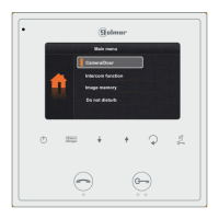
To access the main menu (monitor in standby), s either
of the 2 hidden buttons with indicator LEDs illuminated,
located above the raised dots for the visually impaired see
“TART7/G2+” manual
pres
(
).
In call/ communication an LED shows the location of each of
the hidden buttons.
:
B. Notifications icons:
Do not disturb.
Door opening.
D. Raised dots for the visually impaired.
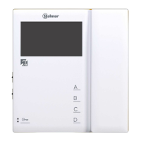
<the function of each hidden button is shown on the monitor
screen with an icon located just above each button see
“TART 7/G2+” manual
(
).
Above the raised dots for the visually impaired /
hidden buttons that access the main menu.
are
the
Above this raised dot is the hidden Start End" /
com unica " .m tion button
Above this raised dot is the hidden Door opening button" " .
F. ophoneMicr .
J. Installation terminals.
*
 Loading...