41
42
INTRODUCTION
INDEX
O Audio system with 4 + N wires installation.
O For installations with several access doors.
O Up to three telephones in the same apartment.
O Up to 20 push buttons modules EL610.
O Electronic call type with selectable call tone on EL651 sound module.
O Acoustic call acknowledgement signal.
O Acoustic busy channel acknowledgement signal.
O Maximum distance between transformer and door panel: 300m. / 2,5mm section.
O Maximum distance between lock release and door panel: 300m. / 2,5mm section.
O Maximum distance between door panel and last telephone: 300m.
O Just 1 TF-104 transformer (12Va.c., 1.5A) will be required for each door panel.
O Door opening timed at 3 seconds.
O A.c lock release operated by relay.
.
.
.
.
2
2
SYSTEM CHARACTERISTICS
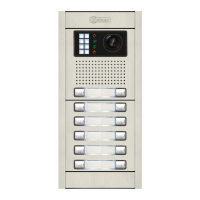
oor panel description.
D
General detail of parts, for assembly the door panel.
Aluminium modules
Electronic
modules
Frame modulesEmbedding boxes
SAFETY PRECAUTIONS
O Install or modify the equipment without the power connected.
O The installation and handling of these equipments must be performed by authorised personnel.
O The entire installation must be at least 40 cm. away from any other installation.
O With power supply:
wDo not use excessive force when tightening the connector screws.
wInstall the power supply in a dry and protected place without risk of drip or water projections.
wAvoid to place it near to heating sources, in dusty locations or smoky enviroments.
wDo not block ventilation holes of the unit so that air can circulate freely.
wTo avoid damage, the power supply has to be firmly fixed.
wTo avoid an electrical shock, neither remove the protection cover nor handle the connected wire in
the terminals.
Check the proper specified input voltage to "PRI" terminals of the transformer.
With telephones:
wDo not use excessive force when tightening the connector screws.
wInstall the telephones in a dry and protected place without risk of drip or water projections.
wAvoid to place it near to heating sources, in dusty locations or smoky enviroments.
wDo not block ventilation holes of the equipments so that air can circulate freely.
Before to connect the system, check the connections between door panel, telephones and transformer
connection.
Do always follow the enclosed information.
w
O
O
O
DOOR PANEL DESCRIPTION
O
O
O
O
To make a call the visitor should press the push button corresponding to the apartment he wishes to
contact. An acoustic tone will be heard confirming the call as the push button is pressed. At this
moment the call will be received at the telephone in the dwelling.
With several access doors, the other(s) door panel(s) will be automatically disconnected: if a visitor
tries to call from other panel an acoustic tone will be heard confirming the system is busy. If the
call is not answered in 30 seconds, the system will be freed.
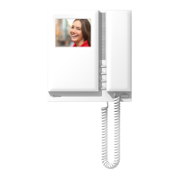
To establish communication pick up the telephone handset. The communication will last for 3 minutes
or until the handset is replaced. Once the communication has finished the system will be freed.
To open the door, press the door release push button at any moment during call and
communication progresses: with one press, the door release operates during 3 seconds.
SYSTEM OPERATION
Introduction...........................................41
Index.....................................................41
Safety precautions...................................41
System characteristics..............................42
System operation....................................42
Door panel description.......................42-43
Modules description....................................
Sound module EL651 ...........................44
Push buttons module EL610A.................45
Door panel installation................................
Embedding box positioning ...................46
Embedding box installation ..............46-47
Assembly electronic modules .................47
Hold the frame.....................................48
Push buttons wiring...............................48
Short connection cable..........................49
Connection cable RAP-610A..................49
Call tone selection................................49
Final adjustments .................................50
Place the nameplate labels ....................50
Close the frame....................................50
Door panel assembly ............................51
Close the door panel.............................51
Power supply installation..........................52
Lock release installation...........................52
Telephone installation..................................
T-900, T902, T900VD, T910 y T910R.....53
T700, T712VD y T710R ........................54
Installations diagrams .................................
Several access doors........................55-56
Replacement..............................................
Conversion table Serie 60/Serie 90.........57
Optional connections..............................58
Troubleshooting hints ..............................58
Compliance...........................................59
First of all we would like to thank and congratulate you for the purchase of this product manufactured by
Golmar.
The commitment to reach the satisfaction of our customers is stated through the ISO-9001 certification
and for the manufacturing of products like this one.
Its advanced technology and exacting quality control will do that customers and users enjoy with the
legion of features this system offers. To obtain the maximum profit of these features and a properly wired
installation, we kindly recommend you to expend a few minutes of your time to read this manual.
 Loading...