25
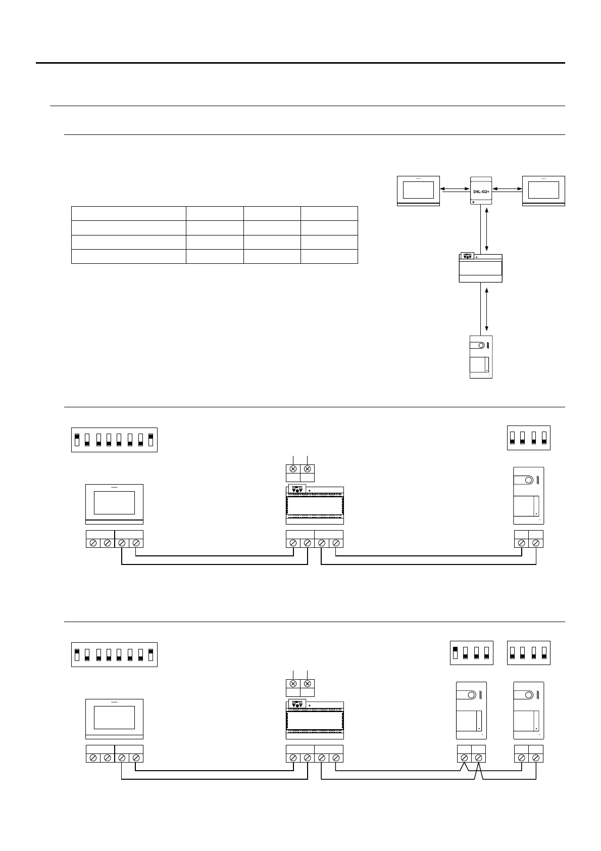
WIRING DIAGRAMS
One apartment with one access panel and one monitor
One apartment with two access panels and one monitor
BUS (M)
BUS (M)
BUS PL( )
BUS PL( )
ON
1 2 3 4
ON
1 2 3 4 5 6 7 8
ON
1 2 3 4 5 6 7
8
L
L
N
N
Mains
100~240V ac
Mains
100~240V ac
APARTMENT 1
MONITORMASTER
BUS BUS
BUS BUS BUS BUS
Cross sections and distances
T cableype of A B C
2 x 0 75mm² ( 18). AWG 30 m 30 m 15 m
60 m 60 m 30 m
60 m 60 m 30 m
CAT5 (*)
RAP GTWIN HF- /
- .The maximum number of monitors per apartment is 4
- The maximum number of monitors in cascade is 12.
A. .Distance between power supply and furthest door panel
B. .Distance between power supply and furthest monitor (or distributor)
C.
.
Distance between a distributor and the furthest monitor connected to one
of its outputs
(*). .Use two twisted pairs for each bus line
FA-G2+
FA-G2+
SOU S5110/ART 7 VIDE ENTL O DOOR RY SYSTEM KIT
BUS INBUS OUT
BUS INBUS OUT
DOOR PANEL 2
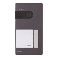
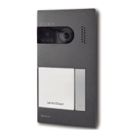
SOUL/1
DOOR PANEL 1
SOUL/1
DOOR PANEL 1
SOUL/1
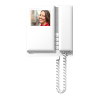
ART 7/G2+
ART 7/G2+
FA-G2+
C C
B
A
ART 7/G2+ ART 7/G2+
SOUL/1
APARTMENT 1
MONITORMASTER
ON
1 2 3 4
ON
1 2 3 4