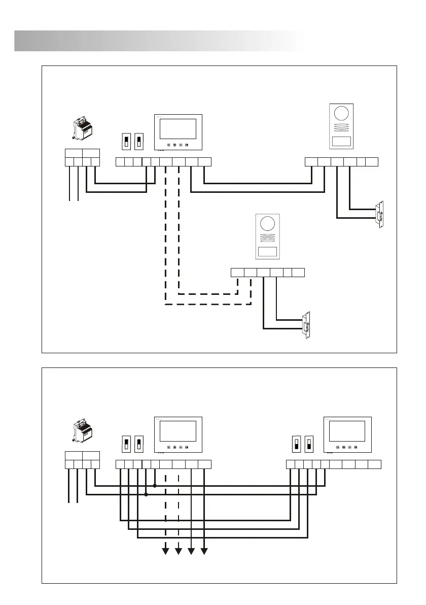
29
SCHEMA D'INSTALLATION
ne ou deux portes d'accès.
U
onnexion d'un moniteur
supplémentaire.C
Vers les plaques de rue
IMPORTANT: Installer seulement le moniteur compatible 370S Couleur (code 11658370).
*
IMPORTANT: Installer seulement le moniteur compatible 370S Couleur (code 11658370).
*
Secondaire
30
ables de sections.
T
Sections jusqu'à
onnexion d'une gâche électrique à courant alternatif, aux
moyens de l'utilisation d'un transformateur TF-104 et un relais R-C
P+ P- CV CV C O B R T MNO
PVS-220
R-3
TF-104
SEC
PRI
~~~~
230Vc.a.
onnexion d'un dispositif auxiliare.
C
P+ P- CV CV C NO
PVS-220
TF-104
SEC
PRI
~~~~
230Vc.a.
En cas de tension supérieure à 12Vc.c./ 1A
entre les bornes C et NO de la plaque,
utiliser un relais.
12Vc.a.
12Vc.a.
SCHEMA D'INSTALLATION
370S
13 2
P1+P1-P2+P2-
+
P+
P+
P-
P-
CV
CV
CV
CV
C
C
NO
NO
PVS-220
PVS-220
12Vc.c.
12Vc.c.
Principal
FA-22
+
__
SEC
PRI
~~
230Vc.a.
__
*
FA-22
+
__
SEC
PRI
~~
370S
13 2
P1+P1-P2+P2-
+
Principal
__
*
370S
13 2
P1+P1-P2+P2-
+
__
*
230Vc.a.
1,00mm² 1,50mm²
1,50mm²
1,00mm²
1,50mm²
Borne 10m. 20m. 100m.
+,
1, 2, 3
CV, CV
P+, P-, P1+, P1-, P2+, P2-
_
 Loading...