23
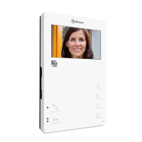
MONITORDESCRIPTION
F
unctionpushbuttons.
H
andlingtheendoflinejumper.
E
L562 moduleforvideoinstallations
withtwistedpaircable.
The end of line jumper is placed on the CN2 connector, that can be located
on the monitor base.
In case of twisted pair cable installations, the end of line jumper is
placed in the EL562 module (see next paragraph).
Do not remove the jumper on monitors where the video cable finish.
Remove the jumper on monitors where the video cable continue.
If the handset is on the craddle allows to see the picture from the master door panel.
If not, allows to establish audio and video communication with the door panel that has
been configurated with the autoswitch-on function. This function is disabled if a
communication is already established.
If the handset is on the craddle, press during 1 sec. to switch the monitor on or off. After
any monitor reset and during the next 45 seconds, all the monitor functions will be
disabled, with the exception of call reception.
With the handset lifted, allows to call to the master porter's exchange.
During call reception and communication progresses allows the lock release
activation, with no dependence on the handset position.
Locate the CN2 connector, that's placed in the monitor base.
To plug the EL562 module, remove the existing jumper and the double
one (JP1) that's place on the right side.
NOTE: on this type of installations, the door panel must be setting with
SW1-3 configuration dip switch to ON; refer to the instructions manual
Refer to the specific installation diagram.
(T631/PLUS ML "page 115" or T500SE ML "page 116") that's enclosed
with the door panel.
24
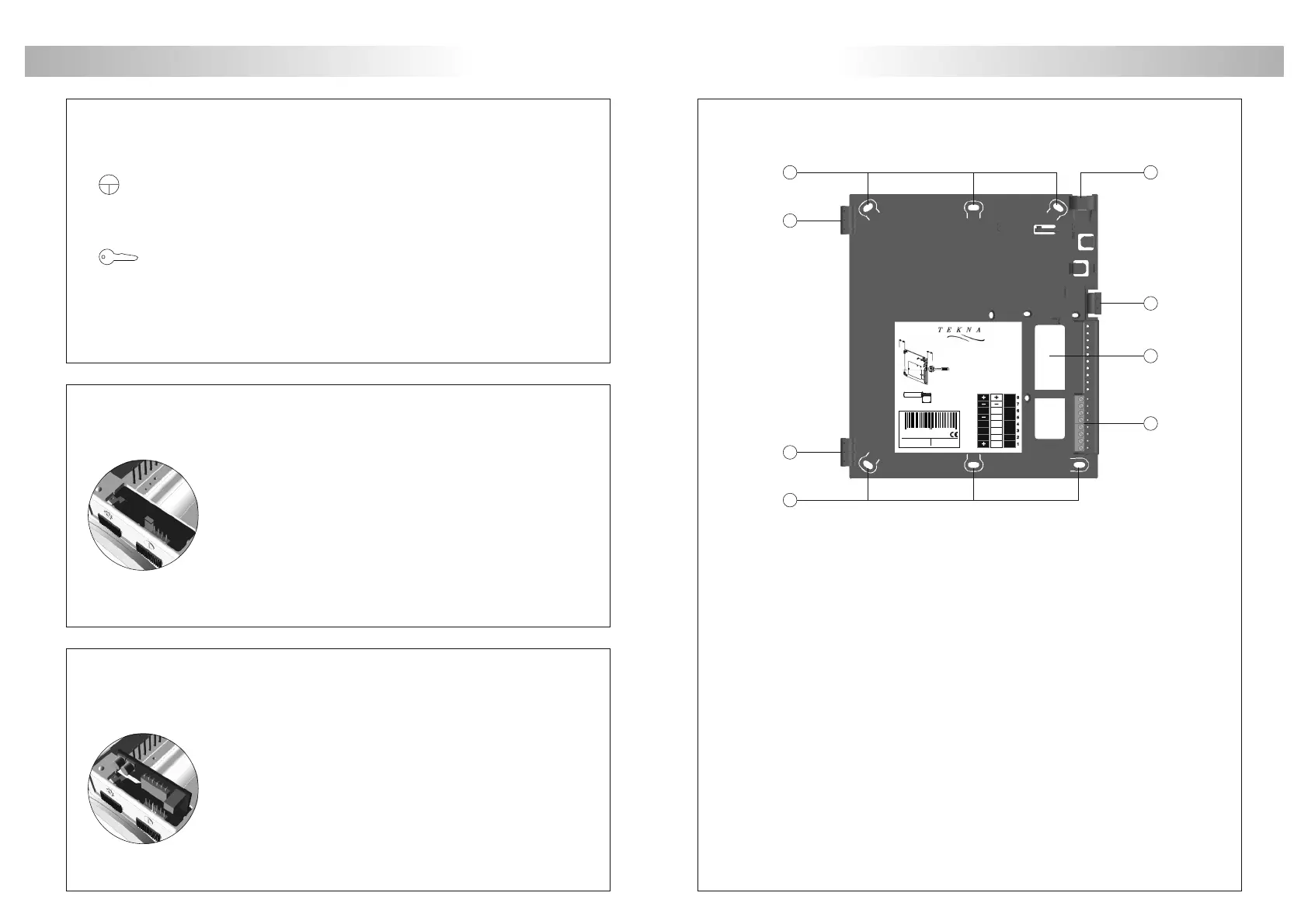
MONITORCONNECTORDESCRIPTION
+, –:
Vin/MP:
Malla:
Vo/VP:
A:
D:
HZ-:
D
escriptionoftheRCTKmonitorconnector.
a.Wallattachmenthole(x6).
b.Monitorattachmenthook(x2).
c.Verticalwiringinput.
d.Attachmentclip.
e.Wiringinputhole.
f.Installationterminals:
positive,ground.
videosignalcoaxialinput.
twistedpairvideosignalinput(MP).
coaxialshield.
videosignalcoaxialoutput.
twistedpairvideosignalinput(VP).
audiocommunication.
digitalcommunication.
doorbellpushbuttoninput.
a
a
b
b
c
f
e
d
Colocarlapartesuperiordelaregletaa1,60m.delsuelo.
Placethetoppartofthemonitorconnectorat1,60m.
fromthefloor.
Distanciamínimaentreloslateralesdelaregletay
cualquierobjetodebeserde5cm.
Theminimumdistancebetweenthemonitorconnector
andtheclosestobjectmustbe5cm.
CO DE 11742 1 80
RE F
RC T K
LO TE
IM P 903 0 12
V2PLUS
PA
PB
Max.
5mm
CABLE
Max.peladodelcable.
Max.peeledcable.
Max.câbledénudé.
Max.aanstriplengte.
UNO
()
*
50mm.
50mm.
Presionarparaabrir.
Presstoopen.
()
*
()
*
8
7
6
5
4
3
2
1
BUS
IN
BUS
OUT
HZ
R5
SA
VP
Vi
-
A/D
MP
Vi+
Malla
Shield
A
D
VP
Vout
MP
Vin
HZ-
8 4 2 9 8 9 8 0 1 1 8 7 5
 Loading...