Do you have a question about the golmar Rock Series and is the answer not in the manual?
Product conforms to essential requirements of European Directives.
Key conditions for proper system operation and interference handling.
Lists key features and specifications of the video intercom system.
Explains how to use the system for calls, communication, and door opening.
Provides essential advice for a correct and safe system setup.
Illustrates wiring for external push-button door release.
Shows how to connect and activate auxiliary devices using monitor buttons.
Diagram detailing connections between door panel, monitors, and power supply.
Specific diagram for the FA-802 power supply unit connections.
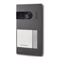
Wiring diagram for the PV-292 video unit.
Table specifying recommended cable cross-sections for different distances.
Instructions for installing the FA-802 power supply unit safely and securely.
Steps for installing the electric lock mechanism on doors.
Guidance on choosing the optimal placement for the door panel's recessed box.
Steps for correctly fitting and leveling the flush-mount box in the wall.
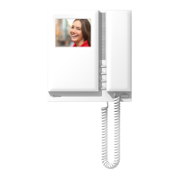
Identifies and describes the parts of the T-705 call station.
Explains the purpose and activation of the function button on the telephone.
Instructions for securely connecting the monitor unit to its mounting bracket.
Guide on how to change the decorative front film of the monitor.
Procedures for fine-tuning audio volume and camera orientation.
Configuration of the time delay for the electric lock release function.
Final steps for securing and closing the door panel after installation.
Details on how to use the monitor's function buttons for various features.
General description and features of the Platea 2 monitor series.
Explains the terminals and connections on the RCPL-2 monitor connector.
Instructions for installing the monitor's wall mounting bracket.
Detailed description of the key features and components of Platea 2 monitors.
Specific actions and functions controlled by the monitor's push buttons.
Identifies the terminals on the RCPL-2 connection bracket for wiring.
Steps for firmly attaching the monitor's connection bracket to the wall.
Guide on aligning the monitor with the connection bracket for installation.
Instructions for changing the monitor's decorative front panel.
Adjusting audio volume and camera positioning after initial setup.
Configuring the duration the electric lock remains activated.
Final steps to mount and secure the door panel.
Guidance on positioning and preparing the recessed box for the door panel.
Steps to route cables and prepare the box for the door panel.
Detailed breakdown of the T-705 telephone's parts and features.
Explanation of the function button's use during calls and system operations.
Schematic showing the complete wiring for an access door system.
Table detailing cable types and their maximum run lengths.
Instructions for safe and compliant installation of the FA-805 power supply.
Recommendations for installing electric locks on metal or wooden doors.
Overview of the video intercom system's key technical specifications.
Step-by-step guide to performing basic system operations.
Crucial advice for first-time installation and system power-up.
Diagram showing how to wire an external button for door release.
Illustrates connecting auxiliary devices to the monitor's terminals.
Wiring diagram for connecting an external button to activate the door release.
Shows how to connect auxiliary devices to the Platea 2 monitors.
Detailed guide for safe and proper installation of the FA-805 power supply.
Guidelines for fitting electric locks onto different door types.
Recommended placement and dimensions for the door panel's embedding box.
Steps for preparing the recessed box, including cable routing and label removal.
Procedures for fine-tuning audio volume and camera orientation.
How to set the activation duration for the electric lock release.
Final steps to secure the door panel assembly after installation.
Detailed overview of the Platea 2 monitor series features and components.
Explanation of the functions and usage of the monitor's push buttons.
Identifies terminals and wiring inputs for the RCPL-2 monitor connector.
Steps for attaching the monitor to its installed bracket.
Guide on how to replace the monitor's decorative front film.
Detailed description of the T-705 call station, including its components.
Explains the role of the function button in activating door opening.
Diagram detailing connections between door panel, monitors, and power supply.
Specific diagram for the FA-802 power supply unit connections.
Wiring diagram for the PV-292 video unit.
Table specifying recommended cable cross-sections for different distances.
Instructions for installing the FA-802 power supply unit safely and securely.
Steps for installing the electric lock mechanism on doors.
Illustrates wiring for external push-button door release.
Shows how to connect and activate auxiliary devices using monitor buttons.
| Brand | golmar |
|---|---|
| Model | Rock Series |
| Category | Intercom System |
| Language | English |