9
26
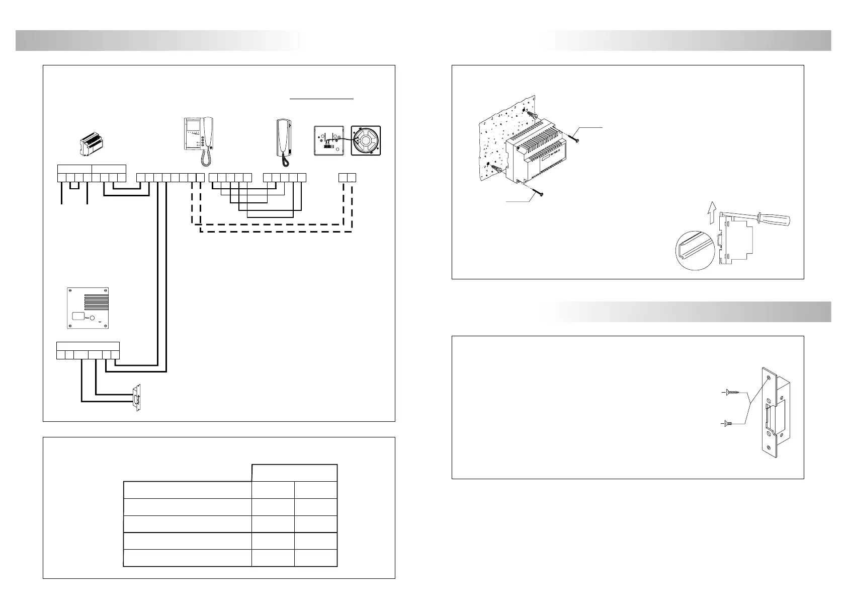
The power supply can be installed on a
DIN 46277 (7 units) guide simply pressing it.
To disassemble the power supply from
the DIN guide, use a plain screwdriver
to lever the flange as shown on the picture.
nstalling the FA-805 power supply.
I
POWER SUPPLY INSTALLATION
DIN 46277
f3,5 x 50
DIN-7971
f3,5 x 50
DIN-7971
LOCK RELEASE INSTALLATION
If the lock release will be installed in a metal door, use a
Ø3,5mm. drill and tap the hole. In case of wood door,
use a Ø3mm. drill.
IMPORTANT: the lock release to be used must be 12Vd.c.
M 4 x 8
f3,5 x 25
DIN-7972
DIN-963
ock release installation.
L
To install the power supply directly on the wall, drill two holes
of Ø6mm. and insert the wallplugs.
Fix the transformer with the specified screws.
The power supply must be installed in a dry and
protected place. It's recommended to protect
the power supply by using a thermo-magnetic
circuit breaker.
na puerta de acceso.
U
Platea 2
abla de secciones.
T
ESQUEMA DE INSTALACIÓN
B2
AM
S+ S-L L
FA-802
SECPRI
220Vc.a.
+
- -
+
P1P2 P3 P4
AM
B1
5
10 0
3
P1
10 3
5 P1 0
S+ S-
Hasta un teléfono y una sonería en
paralelo. No es necesario instalar
un alimentador adicional.
S-45
T-705
Elementos en paralelo
P1P2
L
CN1
CV+CV-
L
PV-292
–, +, AM, AM 1,00mm²
0,50mm² 1,00mm²
Bornes 50m.
Secciones hasta
100m.
L, L
0,50mm²3
0,25mm²0, 5, 10, P1
 Loading...